Designs by Tom Tidhar
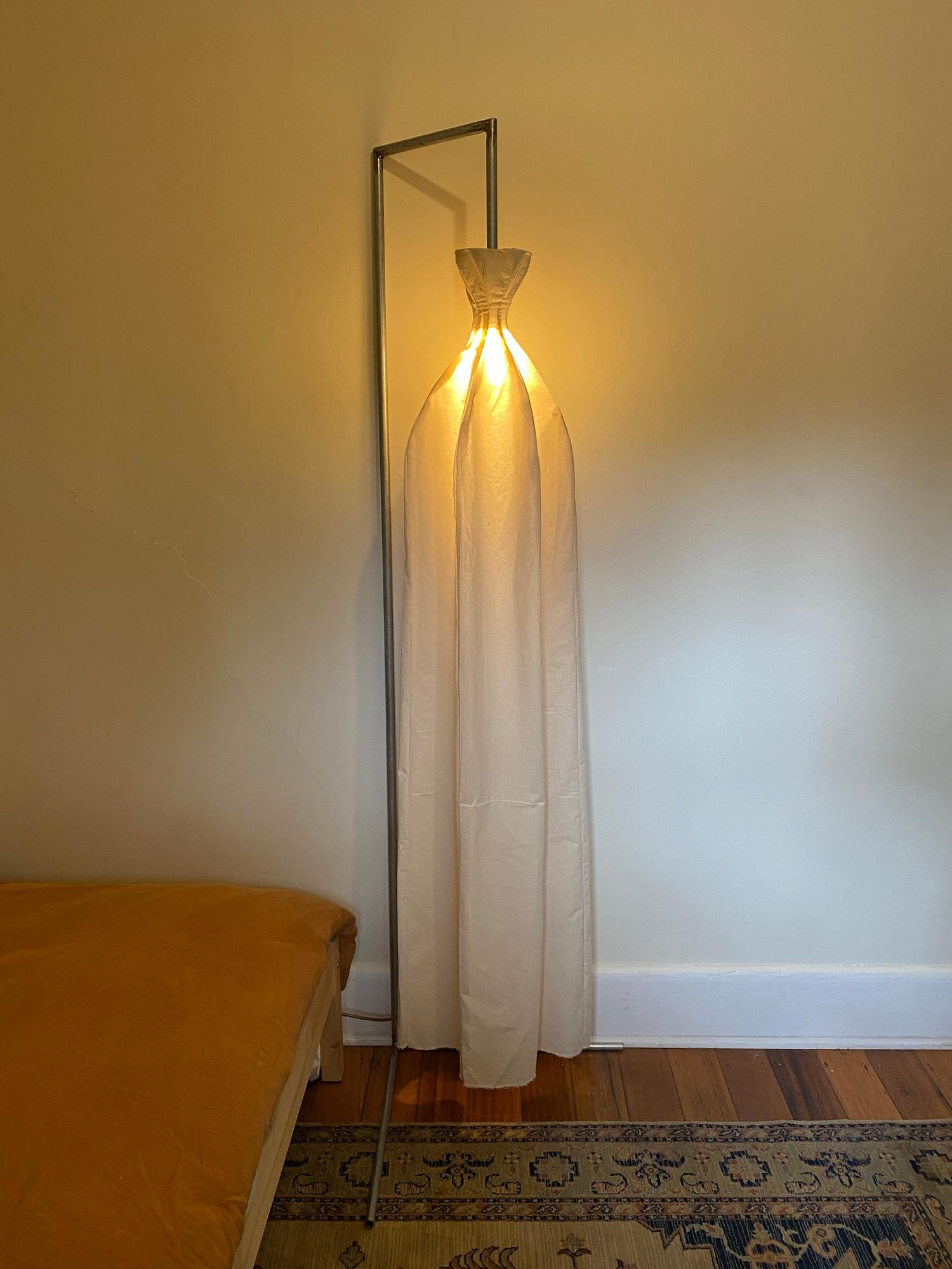
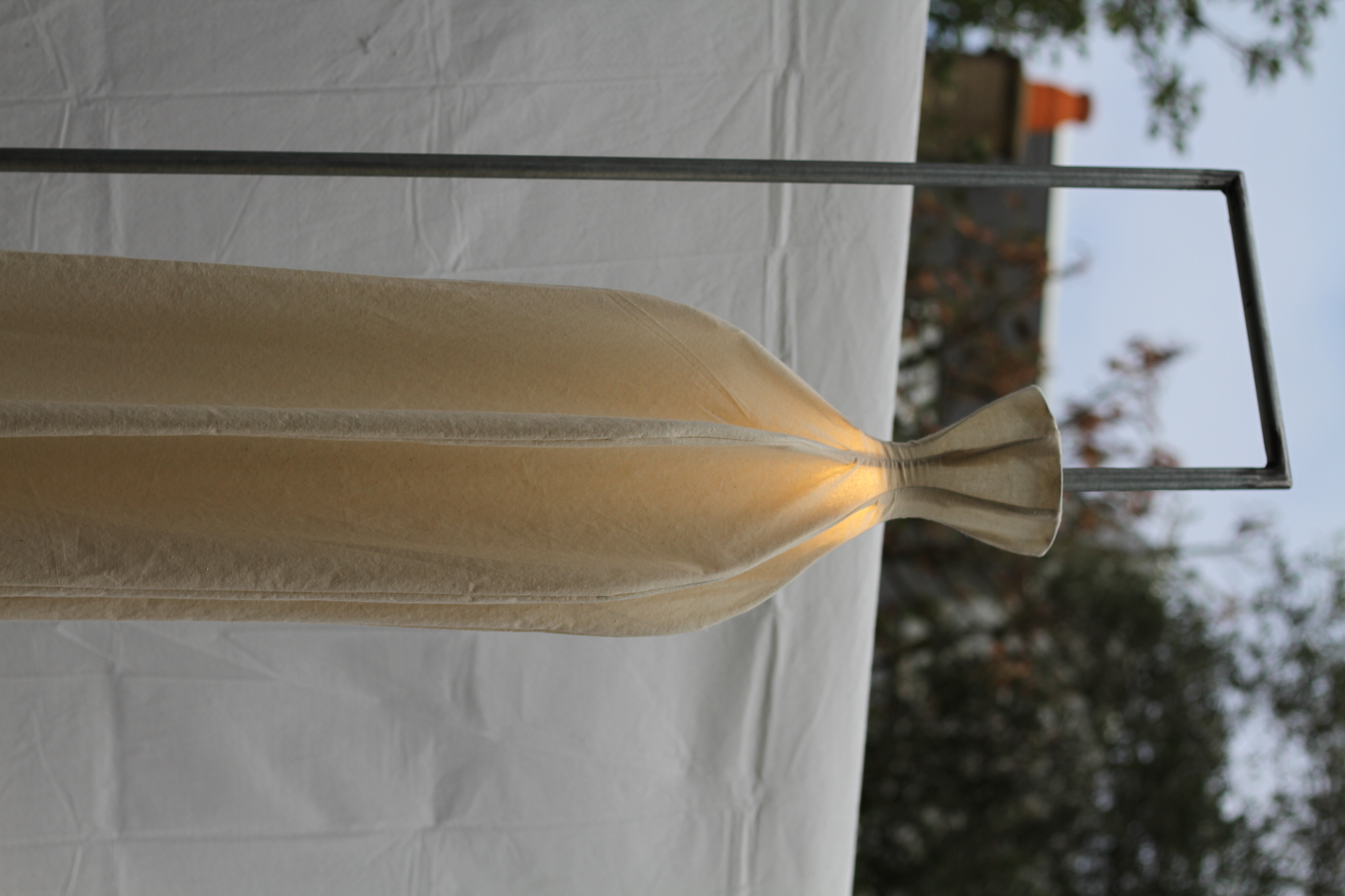
Shade made of wire, calico
This was my first time welding, which was very challenging but rewarding. I used Gasless MIG welding - took some time to dial in the settings (feed rate & current) but got there in the end. Being my first time welding, I inevitably blew a small hole through the steel, after which I turned down the feed rate and got much better results.
The structure for the lampshade is made of wire, bent into shape and soldered together. The shade itself is made out of 7 identically shaped panels, sewed together, with the final panel handsewn directly onto the wire structure.
The wiring runs through the inside of the steel structure, and the structure is grounded for safety. Threading the wiring around the corners was a frustrating process, but got there in the end.
This was a really enjoyable process, and I particularly enjoyed designing and making the flowy lampshade. It holds a beautiful presence in the room, and gives off a nice warm glow thanks to the calico fabric.
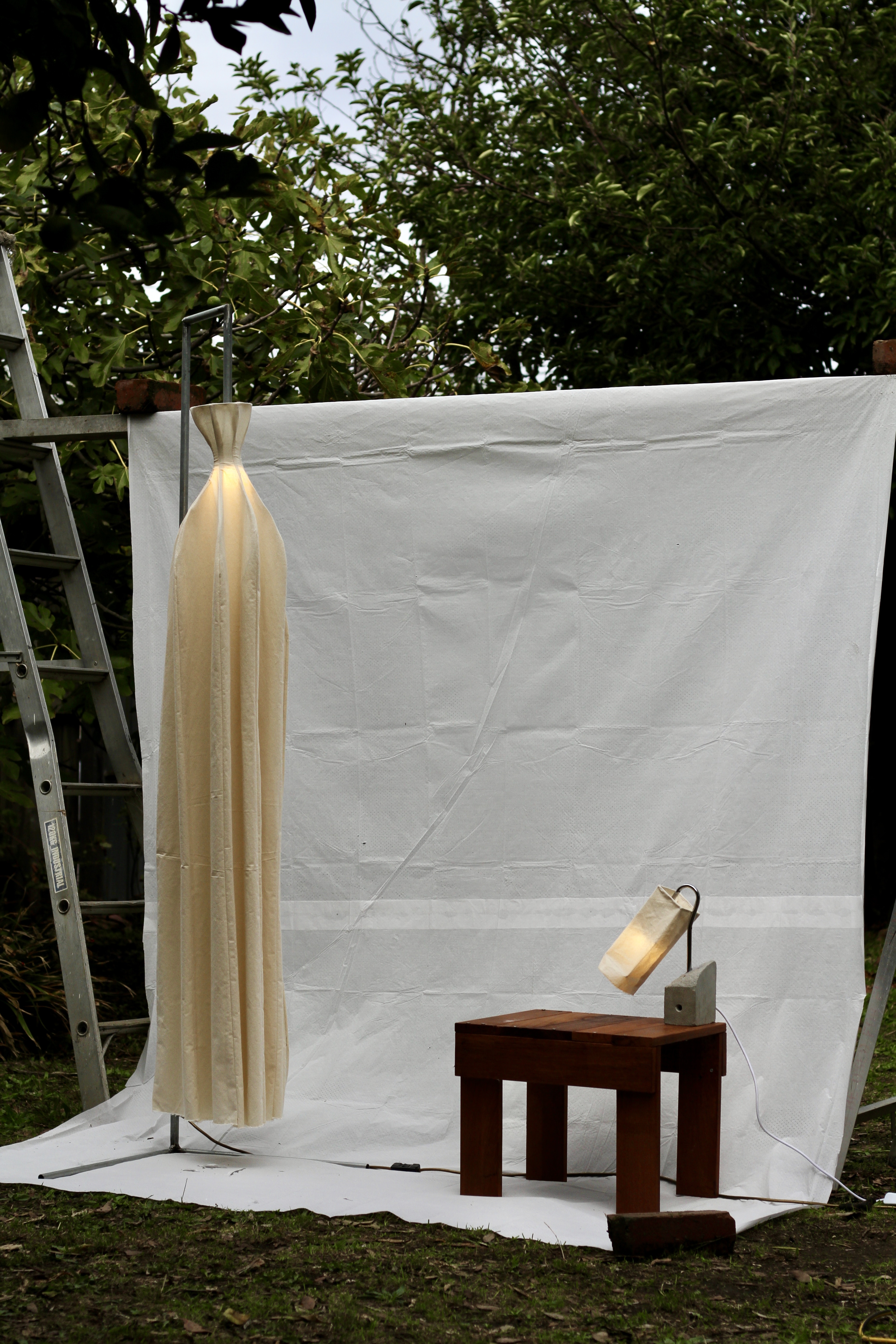
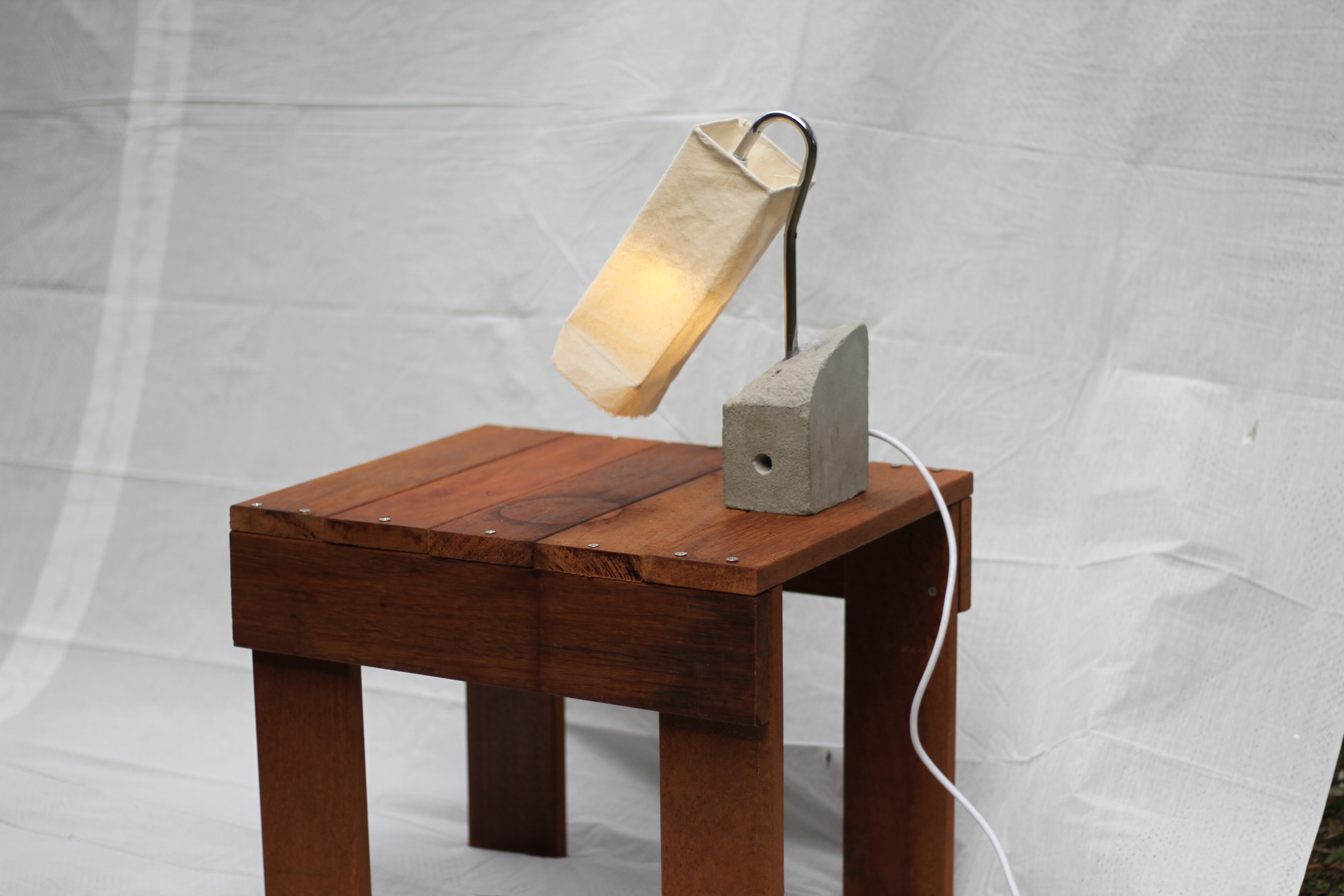
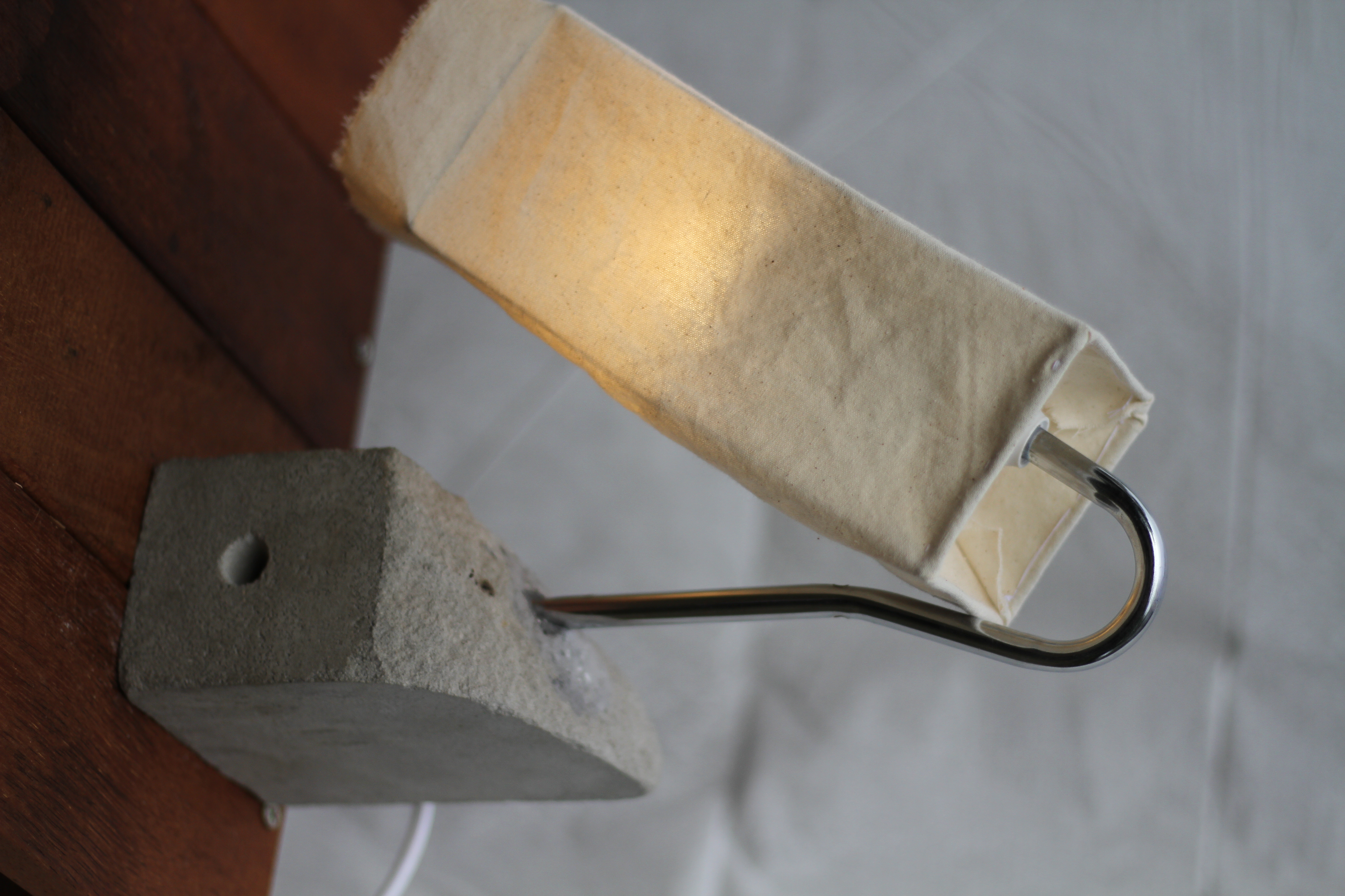
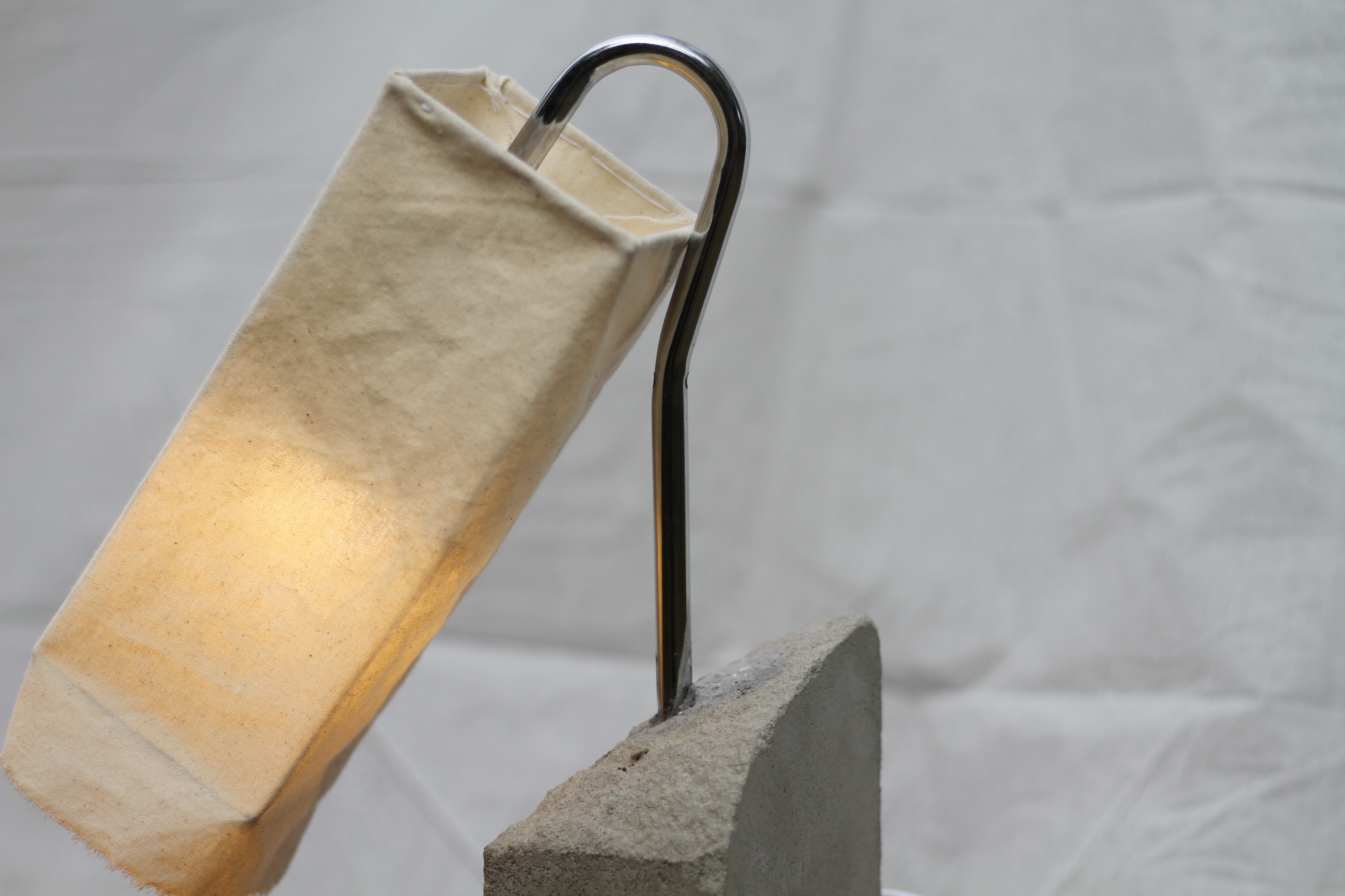
Shade made of wire, calico
The process of making this lamp began when I found an old wire coathanger lying around Mum’s house. It had a strange beauty to it, being made of bent tube steel, which made it easier to wire through the inside. It originally had 3 horizontal pieces threaded through (presumably for hanging underwear or socks) which I removed, keeping only the core shape.
The piece of concrete was an offcut from a bed-base my friend Sivan had made. Having no reinforcement it was too weak for the bed-base, but perfect for this lamp.
The wiring is threaded through a hole in the concrete, and into the coathanger through a v-shaped hole near the bottom, which is all hidden inside the concrete once assembled. The coathanger itself is grounded for user safety.
The structure for the lampshade is made of wire, straightened and soldered. The lampshade itself is made of one piece of calico, made to fit, and hand-sewn at the top to secure to the wire.

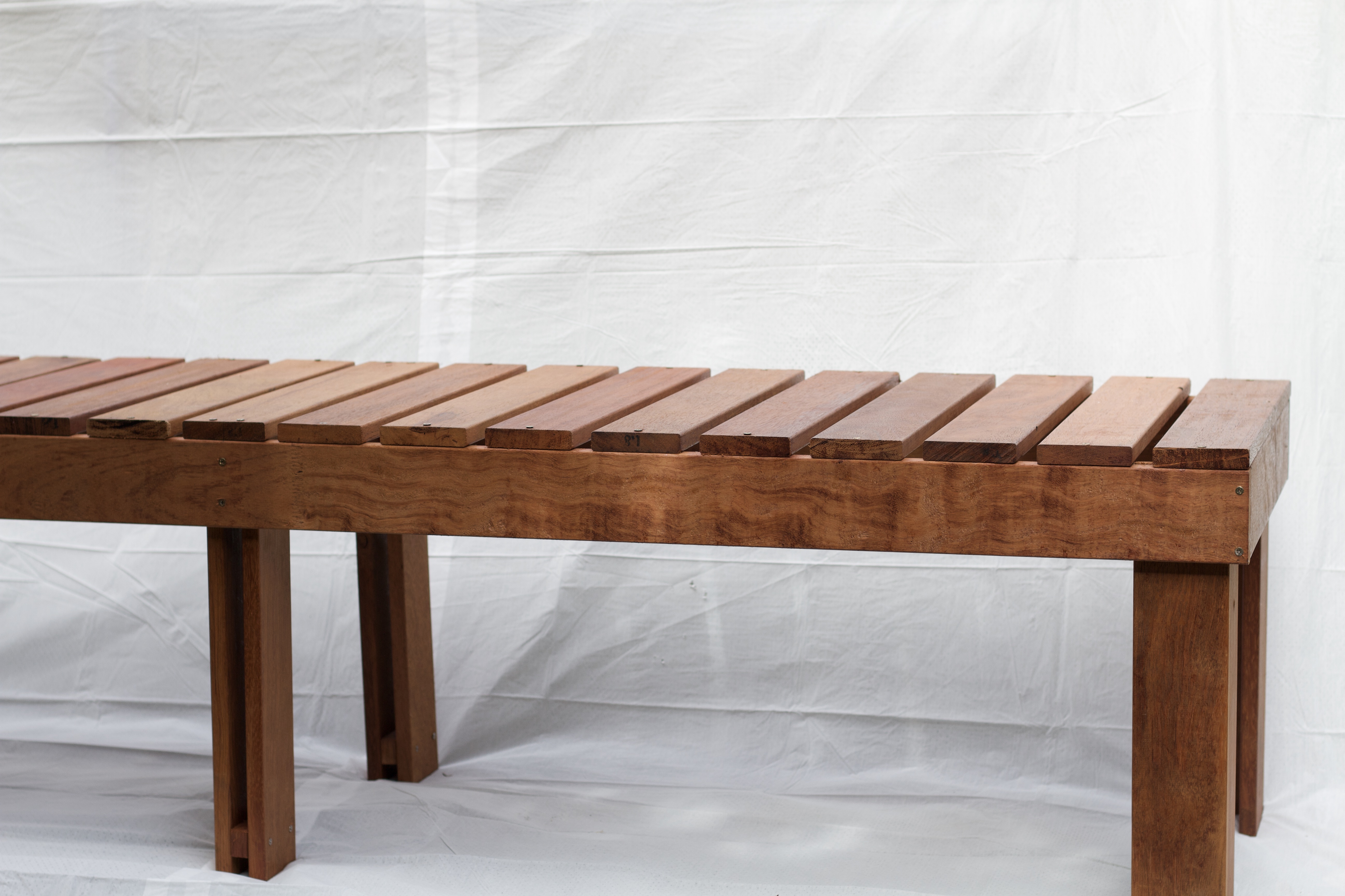
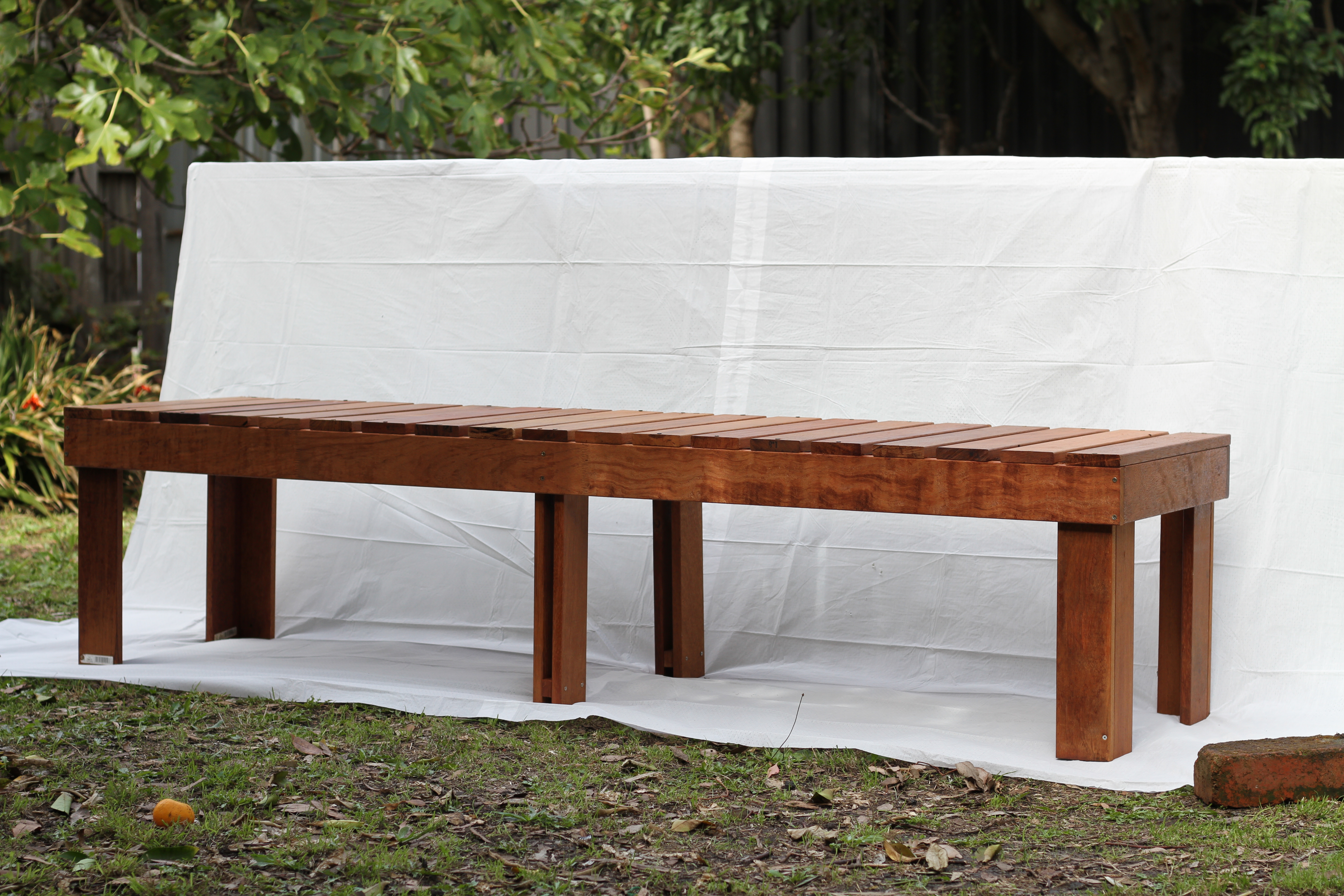
Designed and built with Casey
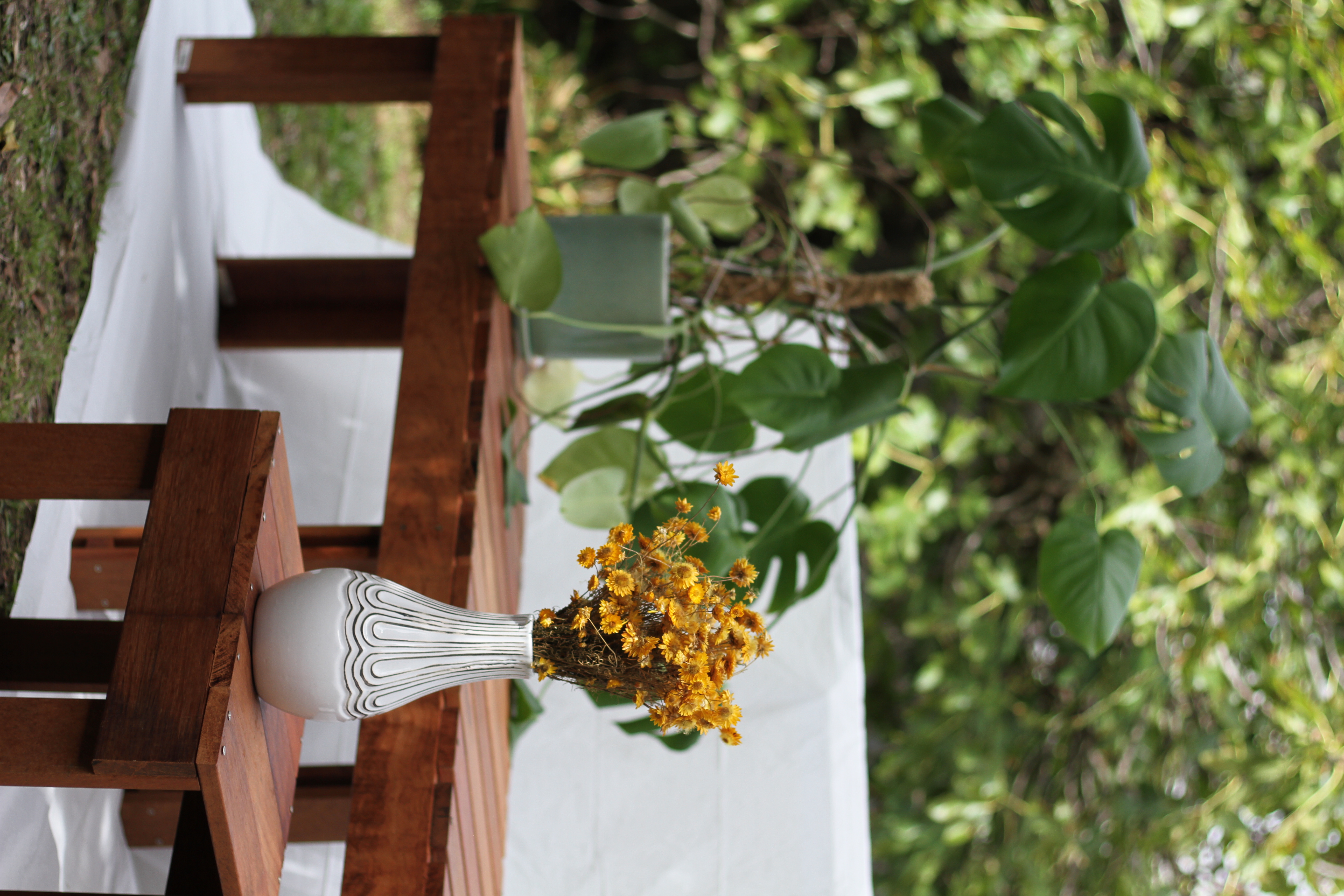
These pieces were built out of Merbau offcuts which were being thrown out, from a renovation happening in the neighbourhood. They were all in beautiful condition, and some of the pieces were over 2m, so I immediately got the car and went and collected them.
The idea for making an outdoor bench came from Casey, my housemate, who had been wanting to replace the outdoor couch which had seen better days.
We opted for a very simple design which, with the help of a drop saw, we were able to make within a few hours. Everything is fixed with timber screws, and is very sturdy.
The coffee table was made using the remaining offcuts - unfortunately I wasn’t able to snap pics of the coffee table before a kettle had burned a dark circle into the wood.
Designed with Ray
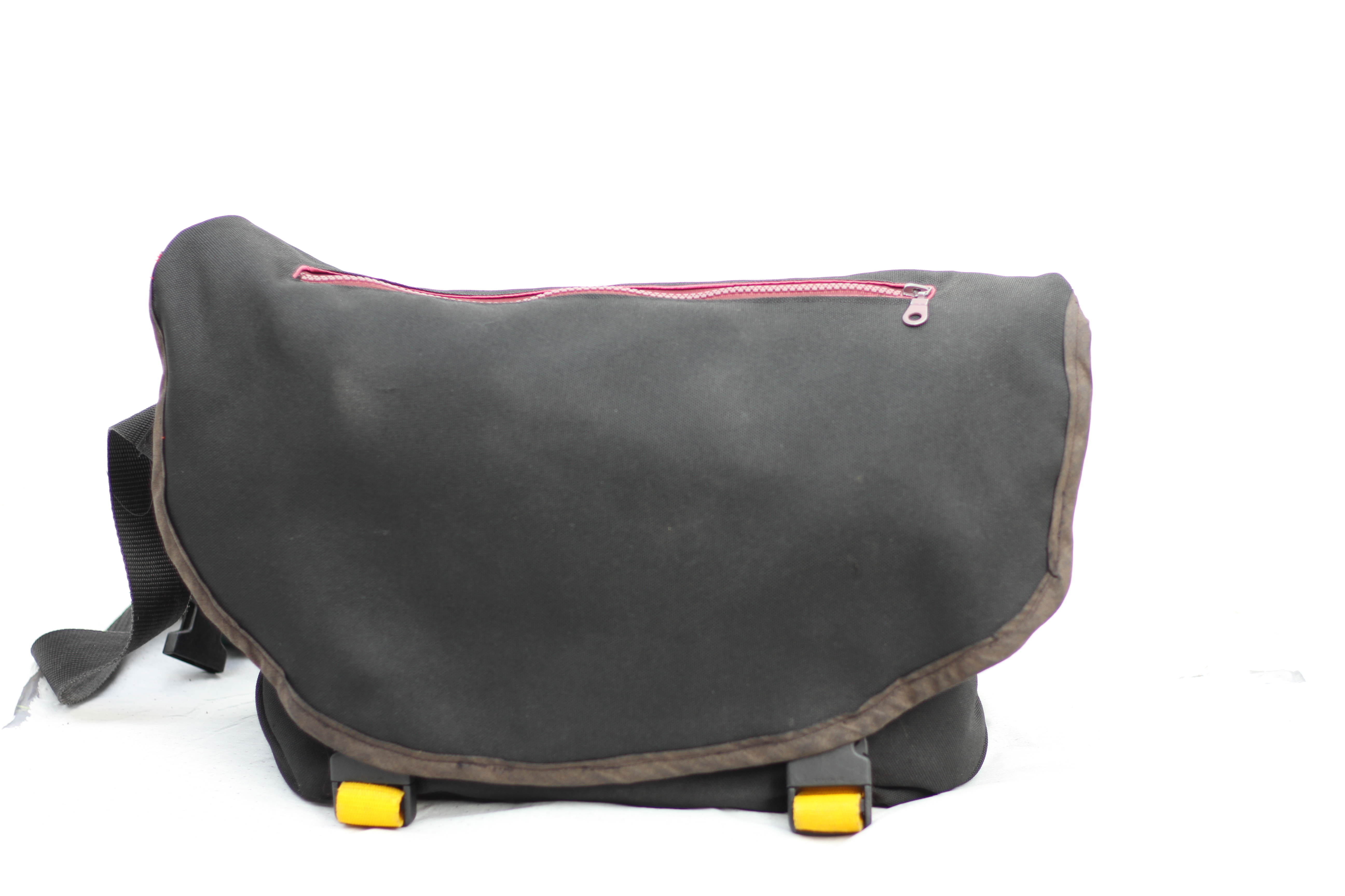
I made this bag when I first moved to Milan, as I was starting a Masters degree at the Politecnico and I wanted a messenger bag I could wear daily. The pattern for the bag was made by my friend Ray (who now runs a bag company @rayxbagz), which had the general outline of the main shape. I did all the sewing using a standard sewing machine.
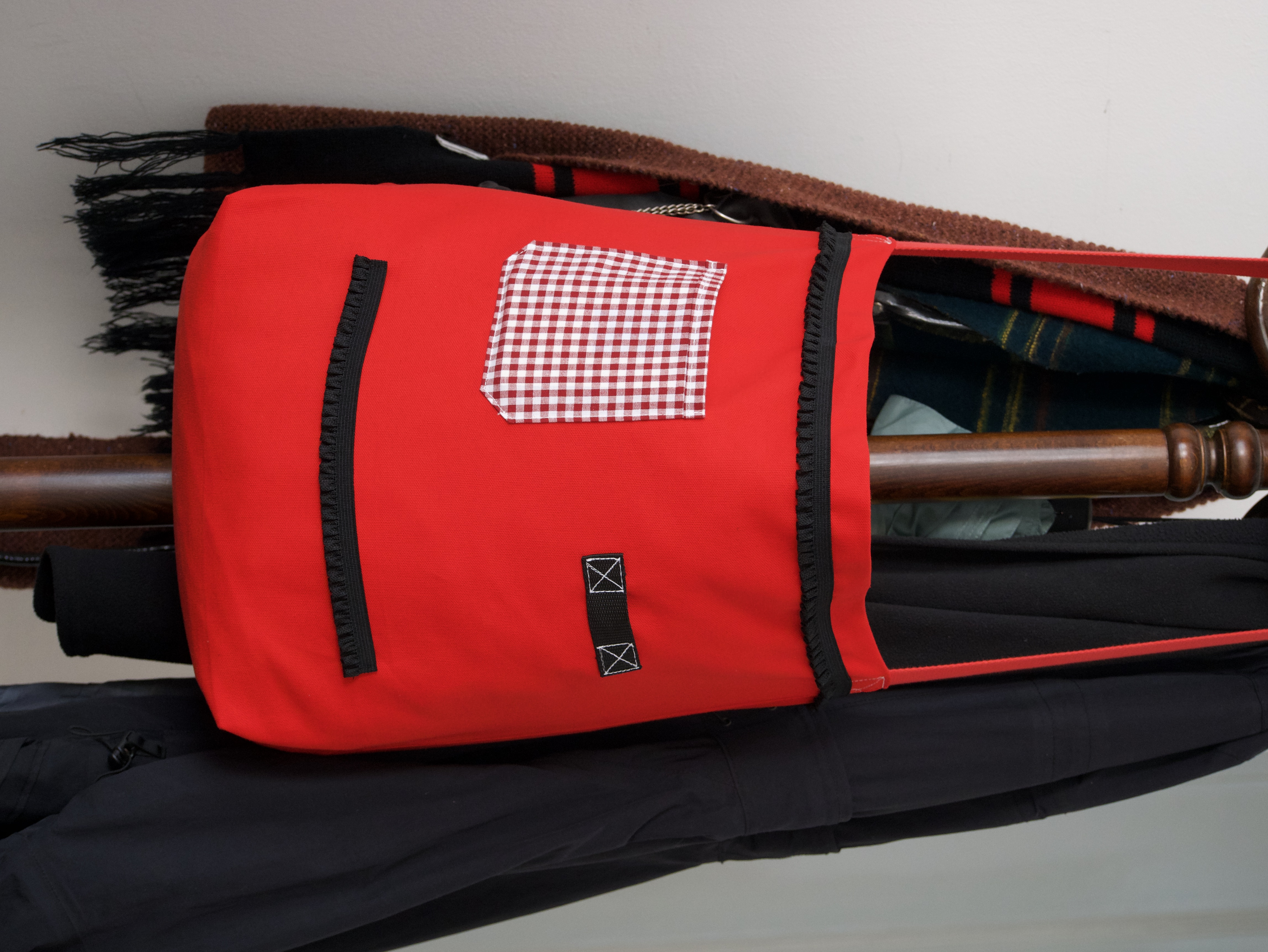
The bag has two main layers, an inner (red) and an outer (black), with spacer mesh along the inside of the back. There’s two internal dividers: one for the laptop/books, and the other for a water bottle, pen, and small trinkets. There’ a zipper pocket along the front, as well as another quick access zipper pocket on on the top. The shoulder strap is adjustable, and there’s a second strap which connects under the arm, perfect for securing the bag in place while riding.
All the edges are bias bound, so that there are no raw edges showing - this was the part that took the longest, as I didn’t have a binding machine so I had to use a normal sewing machine with a binding foot.
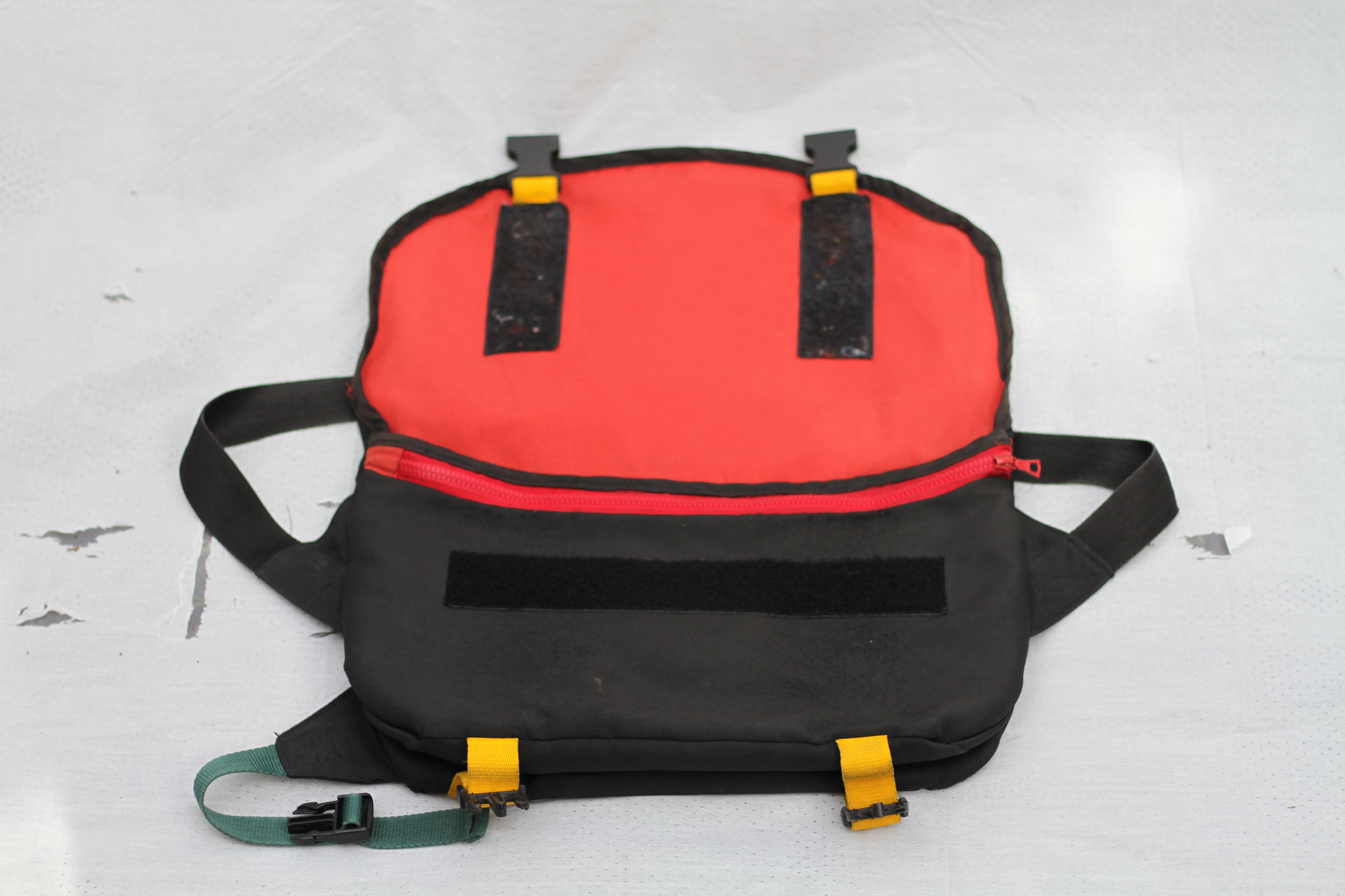
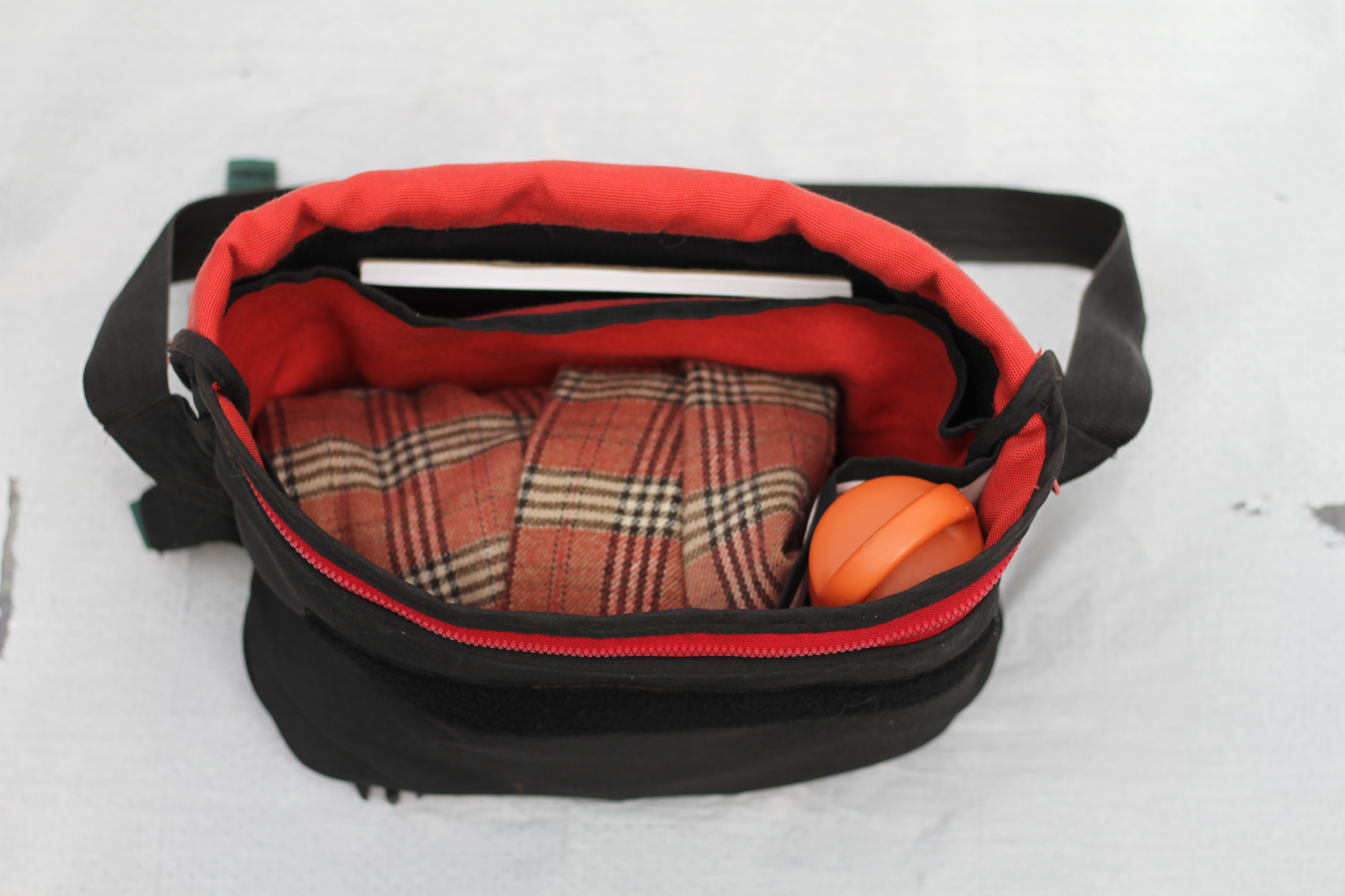
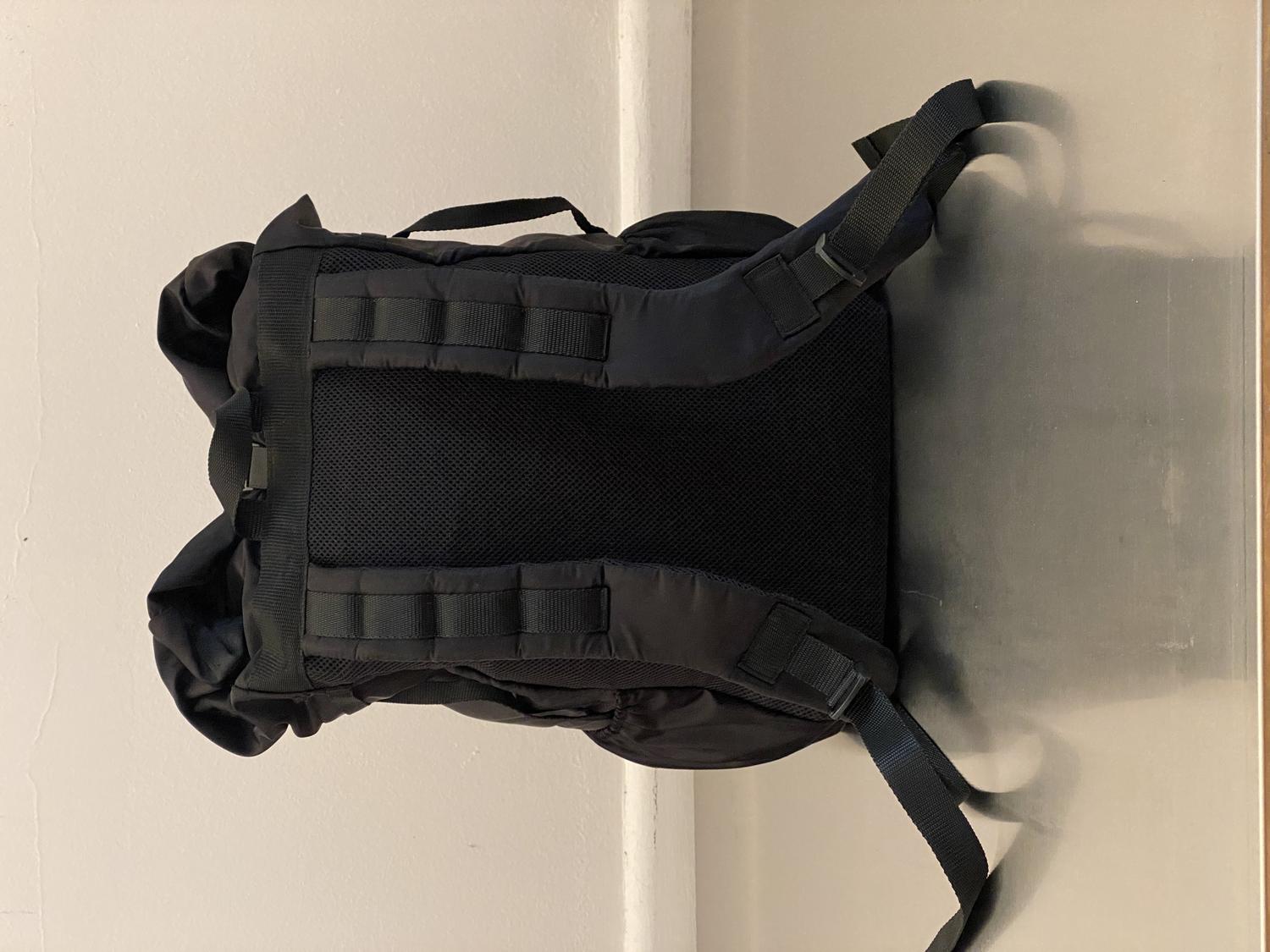
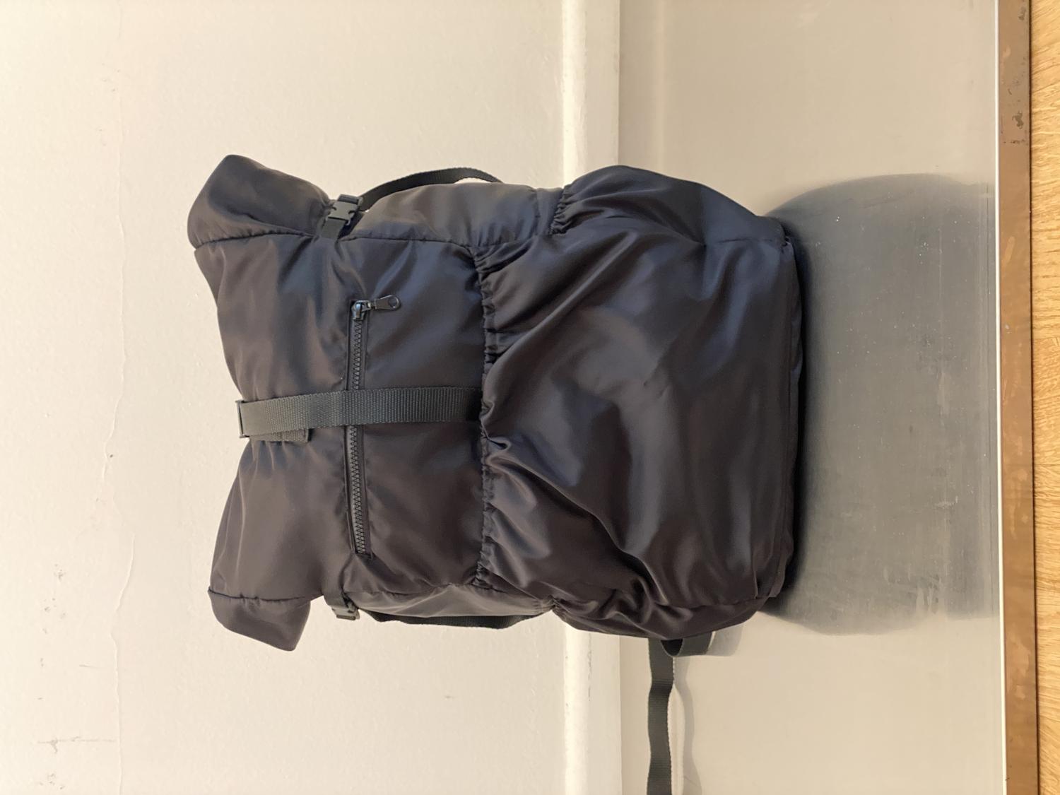
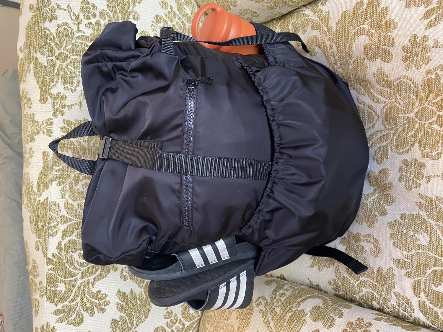
I wanted to make a bag which would perfectly fit the Ryanair carry on policy, but also be useful for an overnight hike, and this is what I came up with. I created the pattern for each section of the bag (including shoulder straps, pockets, etc) and sewed it together using a household sewing machine. It is bias bound everywhere with no raw edges showing. The majority of the bag is made of nylon so it’s ultralight, and the rolltop makes it adaptable for different purposes.
On the outside, it has three elastic pockets (two on each side, and one big one at the front) as well a strap on each side (for holding a tent, trekking poles, a baguette, etc) and an easy access zipper pocket. On the inside (see inside-out photo) there’s two zippered pockets, as well as an elastic laptop section. The back is padded with spacer-mesh, and the straps are filled with foam padding, have nylon webbing for clipping things on, and are adjustable.
To make the shoulder straps was a little tricky - I had to sew them inside out, then turn them the right way around and manually stuff foam padding in (a sisyphean endeavour, although I got there in the end). A wide piece of nylon webbing holds the straps at the top, ensuring they don’t rip.
There are two key things I would change with the design of the bag. First, is adding a pocket for an insert along the back of the bag - this would give the bag a bit more structure. Second, I would attach the shoulder straps to the top of the horizontal webbing, not to the bottom - this way, the straps would follow the wearer’s shoulders a bit better, and the bag could sit more naturally on the wearer’s back.
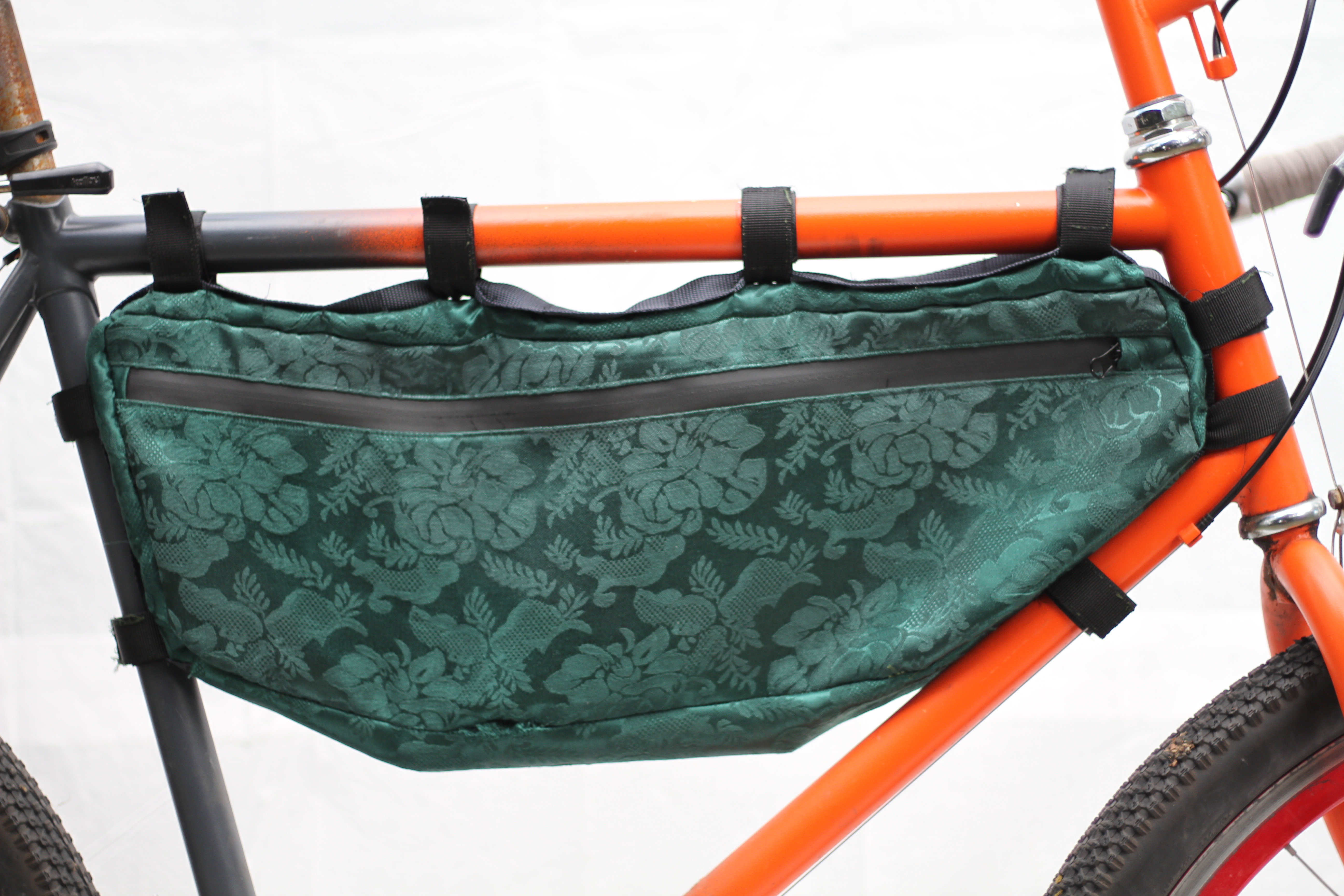
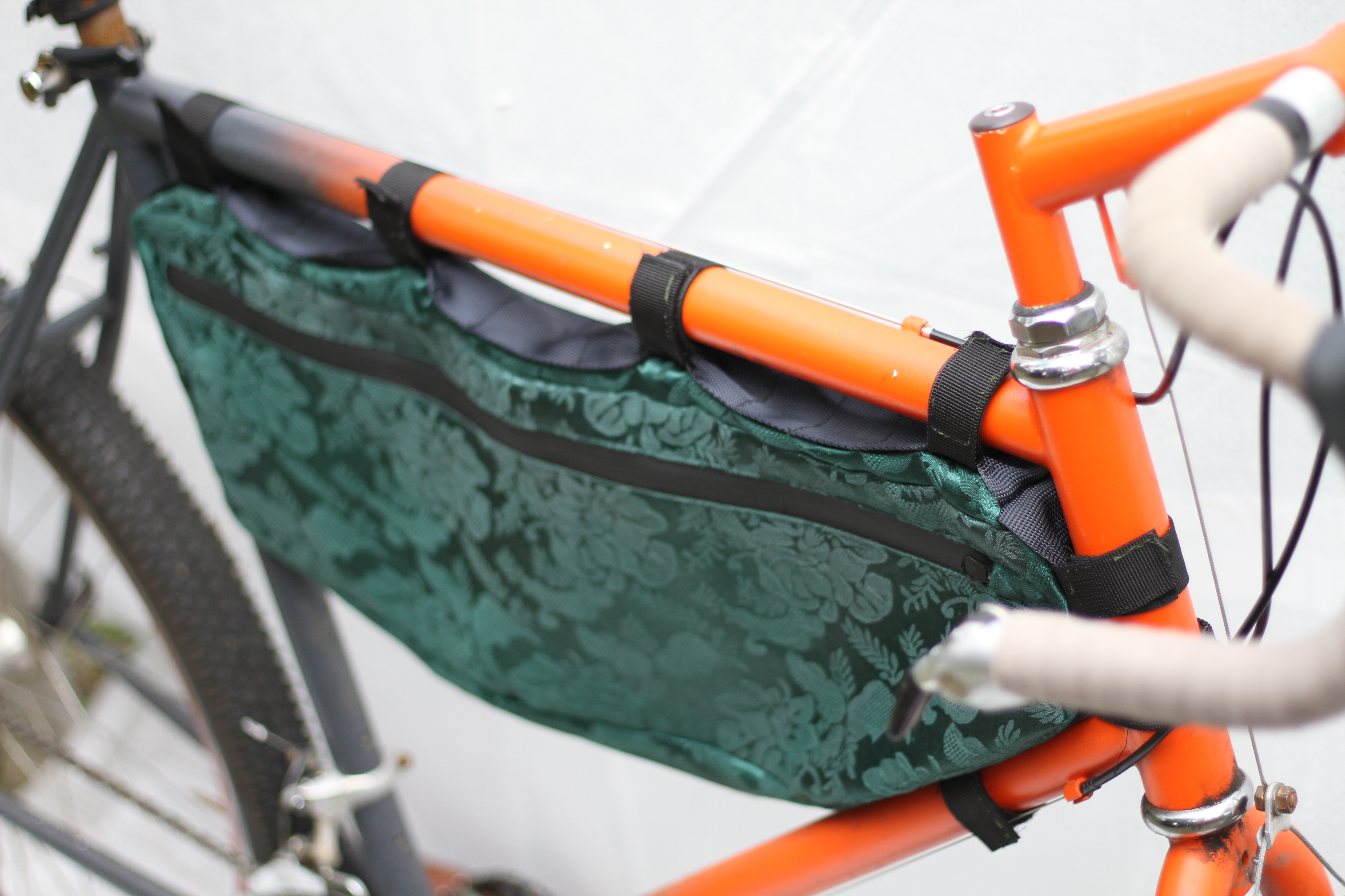
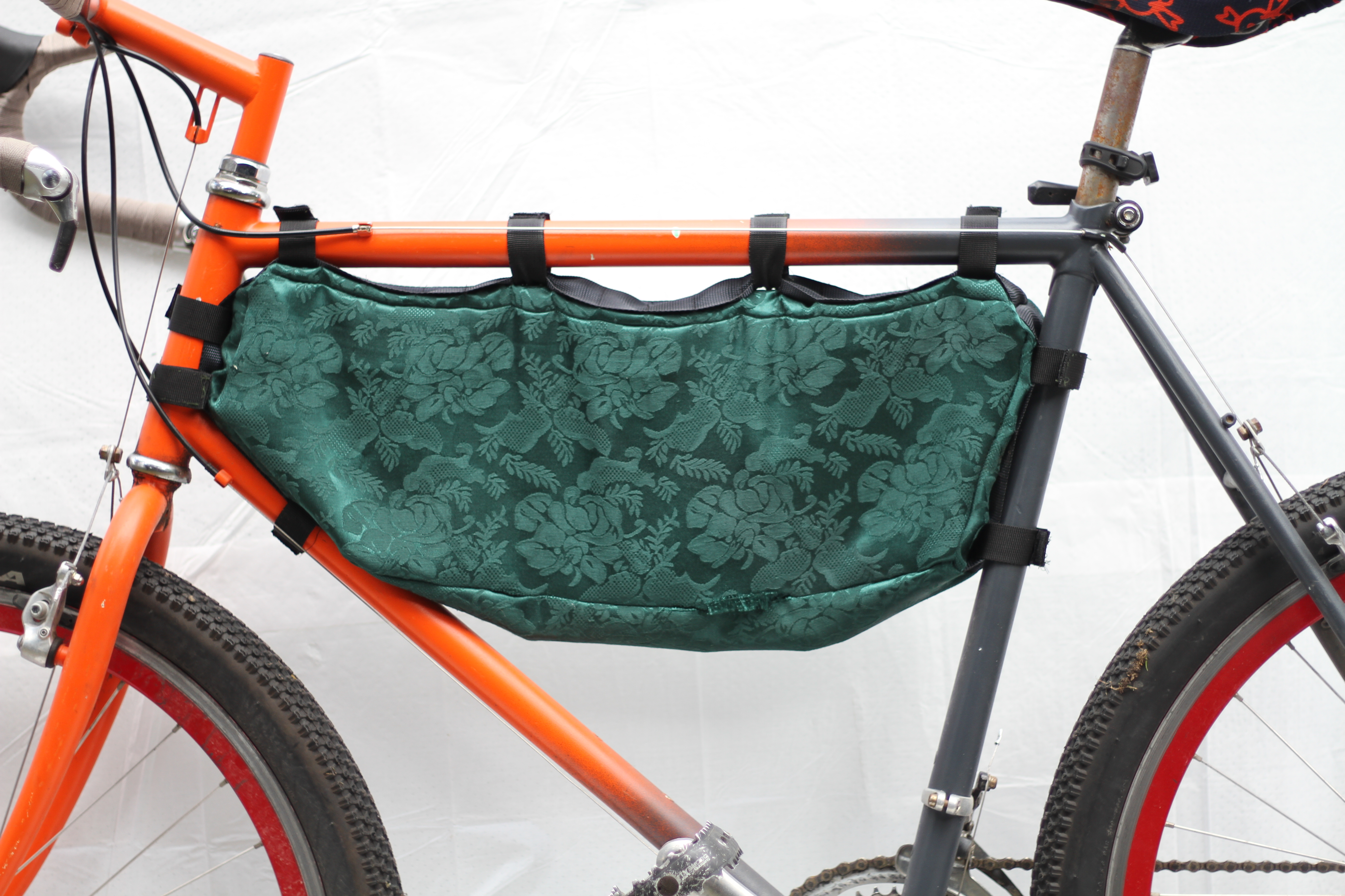
I made this bag for a bike which was lent to me by Ray, for the summer. I found the fabric on the side of the road and loved the pattern so I wanted to see what I could do with it.
I’ve made a half-frame bag before, so I was familiar with the process and it all went smoothly. To be honest, it’s really not the best fabric for the job - after a few weeks of use the bag started to visibly sag, and even started fraying a bit because I didn’t bind it. Next time I’ll definitely be double-layering it with something a bit stronger, and binding it together to keep it from fraying.
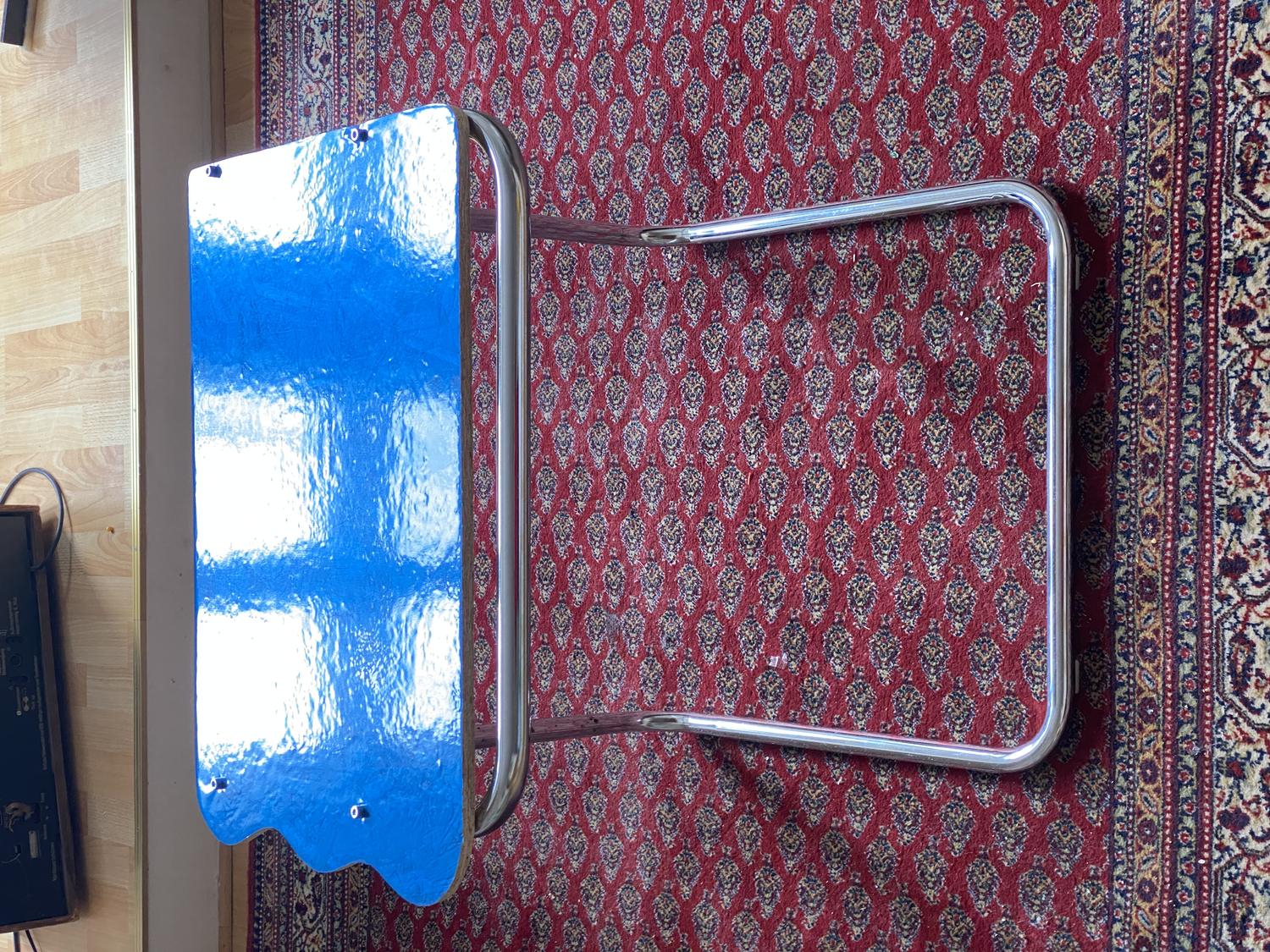
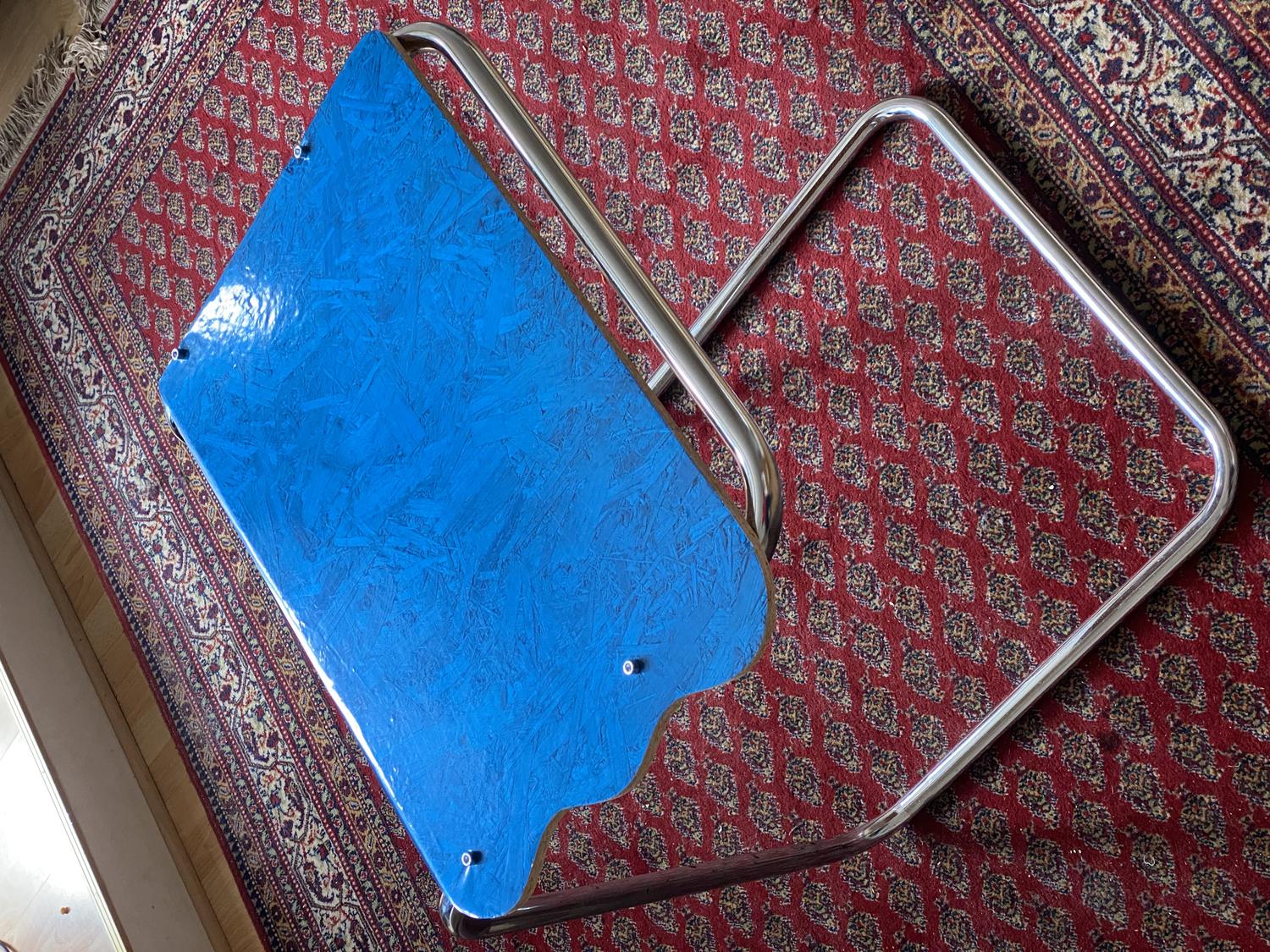
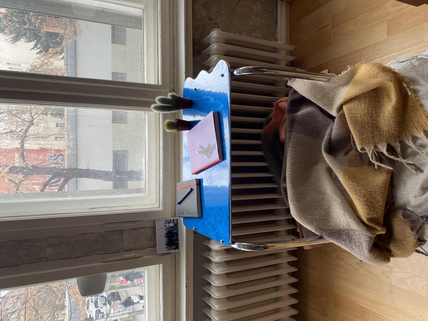
Great for getting cozy in front of the window and reading, or to eat dinner at while watching telly on the couch.
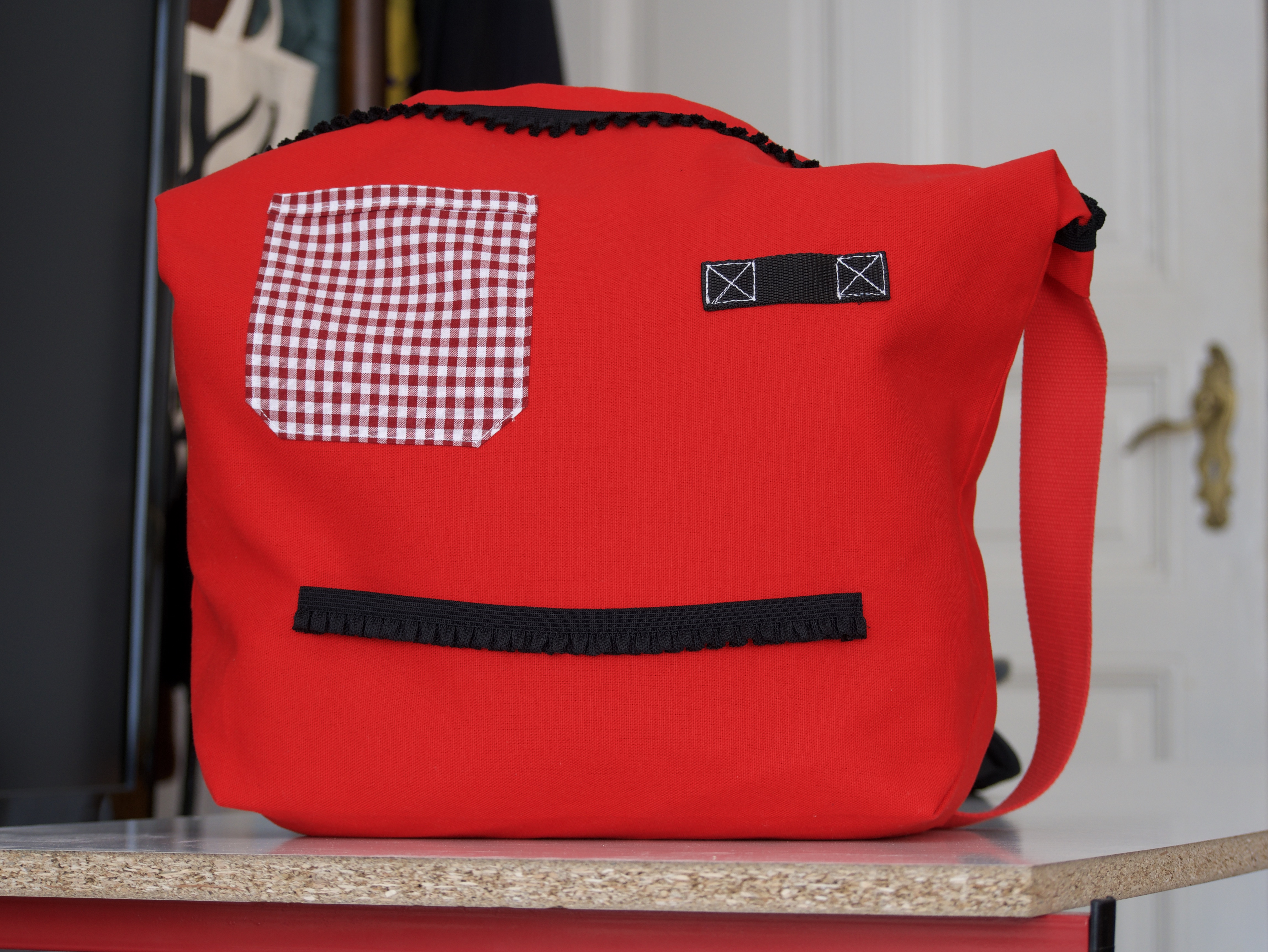
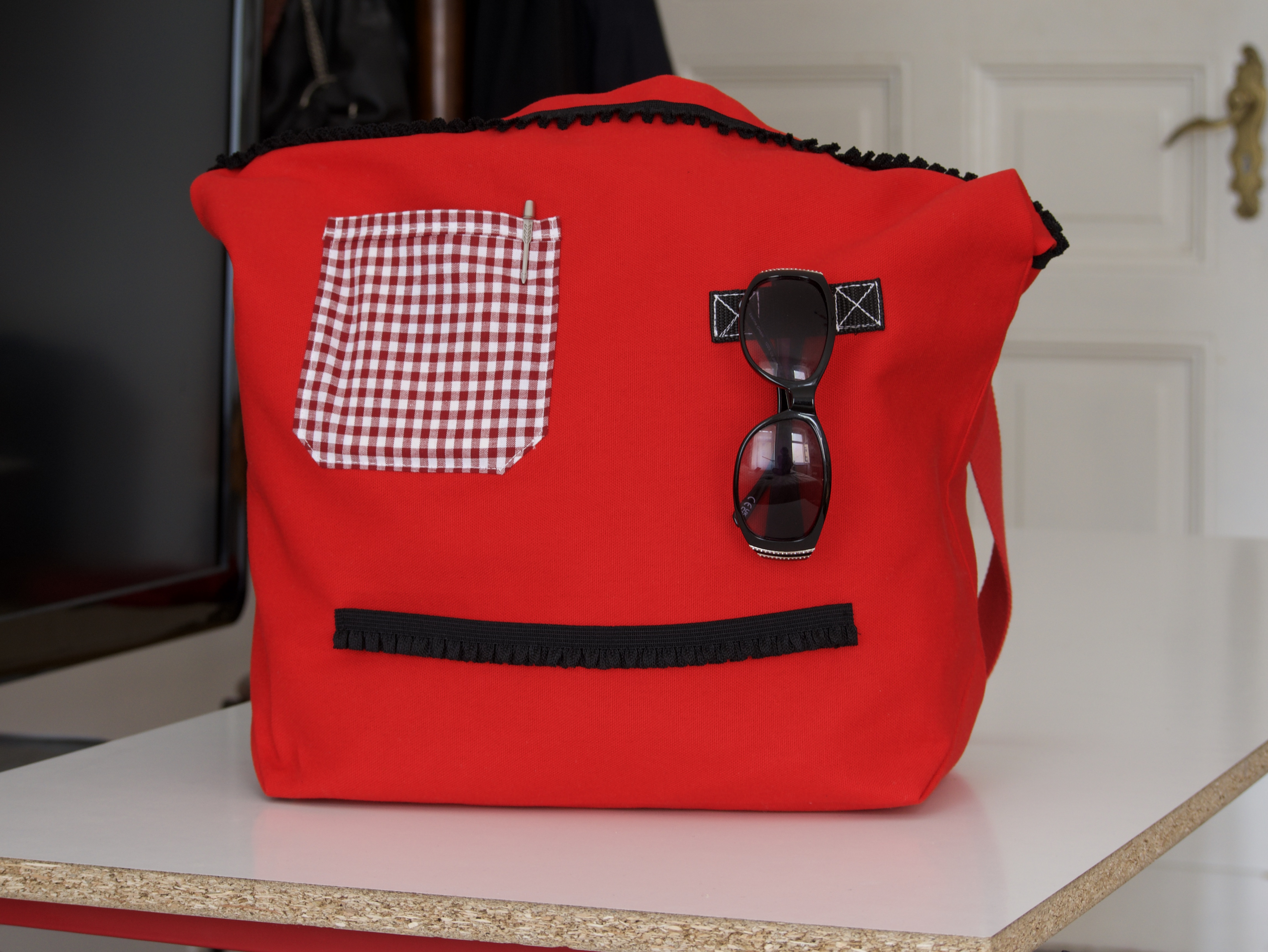
Wanted to make a bag which would hold my things but also make faces at me ;)
With an adjustable smile.
Base made of PLA (3D printed)
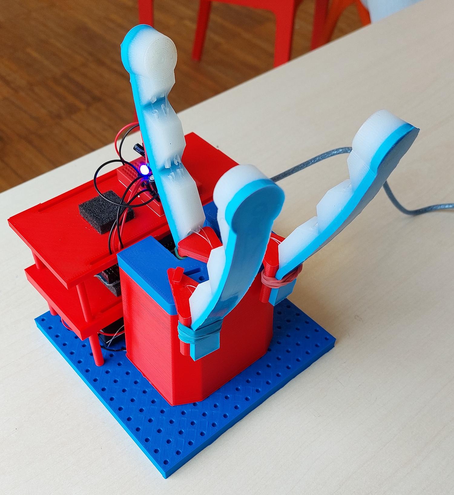
This was a design and fabrication project for a university course - which I created with 3 other students (Enrico, Elia and Andrea). The task was to create a “soft gripper” with one actuator. We completed this project from start to finish, with many steps involved in the process: concept formation, mold design, material selection, silicon casting, base design, 3d printing, motor selection, construction, testing, evaluation.
The idea behind the soft gripper is to be underactuated (only one motor) and thus obtain its versatility from compliance instead of control. The actuation is achieved through “tendon actuation” - tendons are threaded through each finger, and shortening of these tendons (by spinning the tendon around the motor shaft) causes a “closing” of each finger, much like a human finger.
In fact, the design was primarily based on the human finger (and hand), from which we also derived the geometry, the fingerprint pattern, and which assisted us in material selection. We used three different types of silicon in each finger - SmoothSil 850, Dragonskin 10, Dragonskin 30 - each serving a different function.
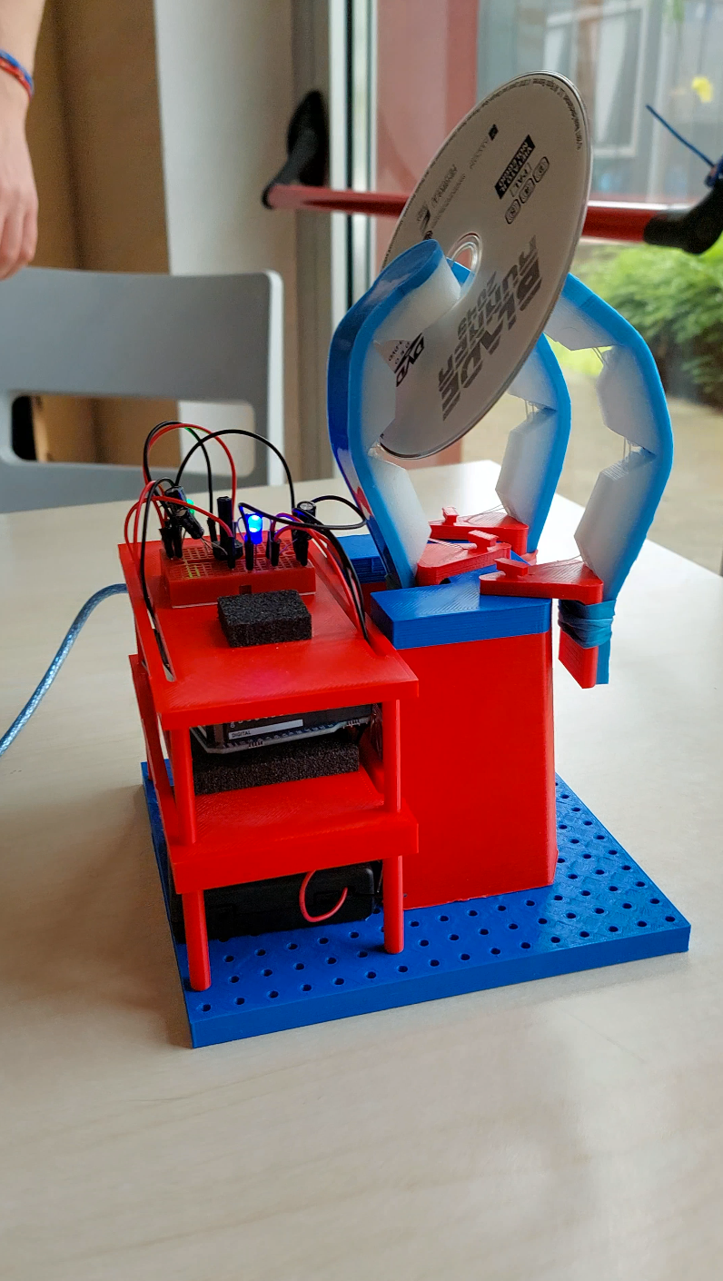
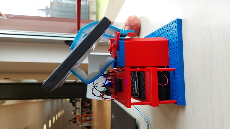
The implication for a soft gripper like this is that it is able to hold fragile objects (e.g. gripping a CD, see gif above) with a very simple control method. The compliant material allows the fingers to wrap around each object, thus maximising surface area and therefore eliminating stress concentrations.
Further development would involve improvement of the base shape (e.g. making it to-fit rather than modular), further actuation optimisation (trade-off between range of motion and mechanical advantage), and testing the gripper in various conditions (in particular underwater where the fingerprints would play a larger role). More than anything, this project was intended as a proof-of-concept, which we clearly demonstrated.
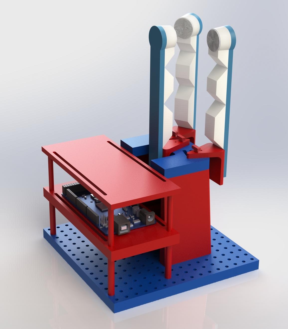
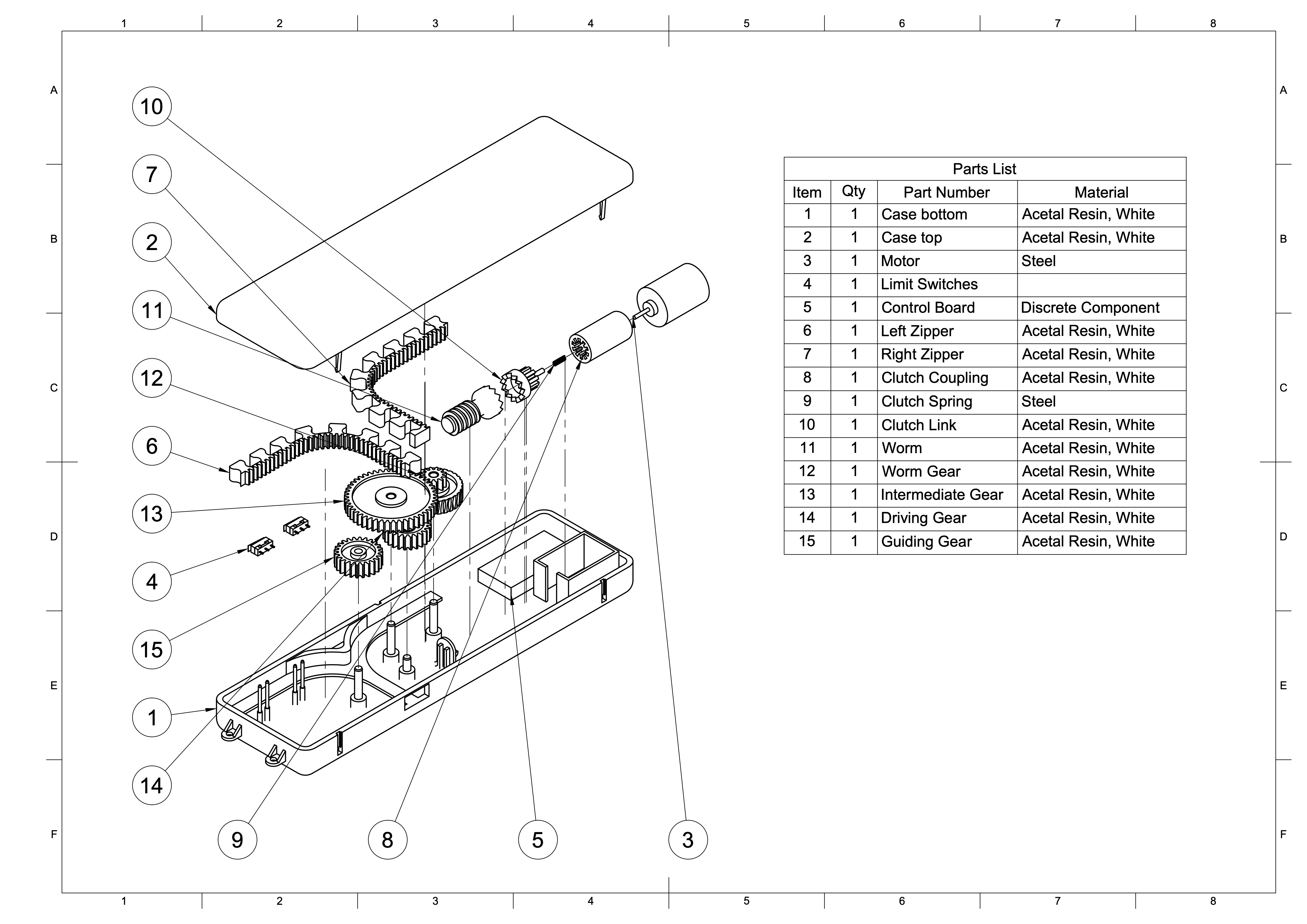
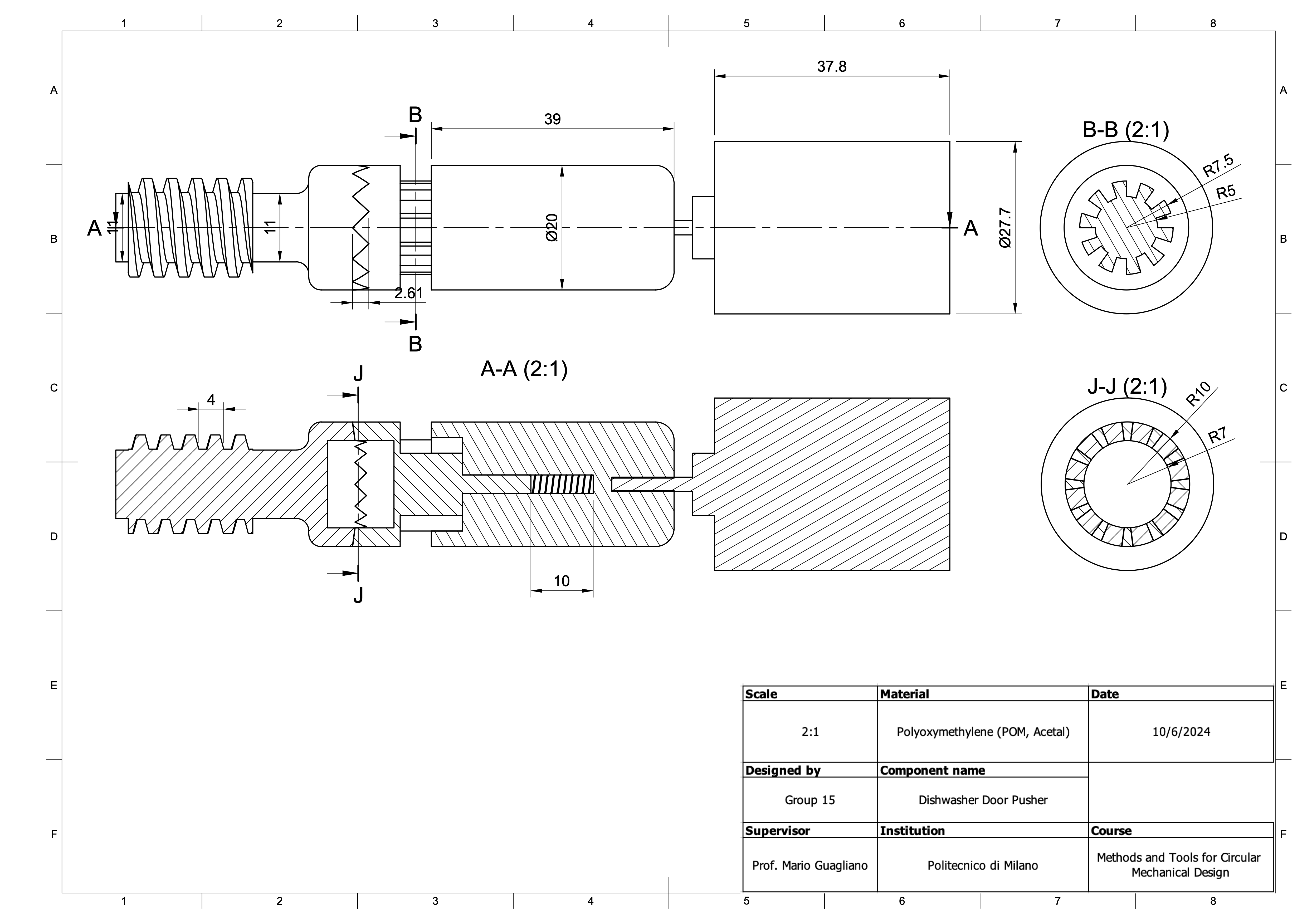
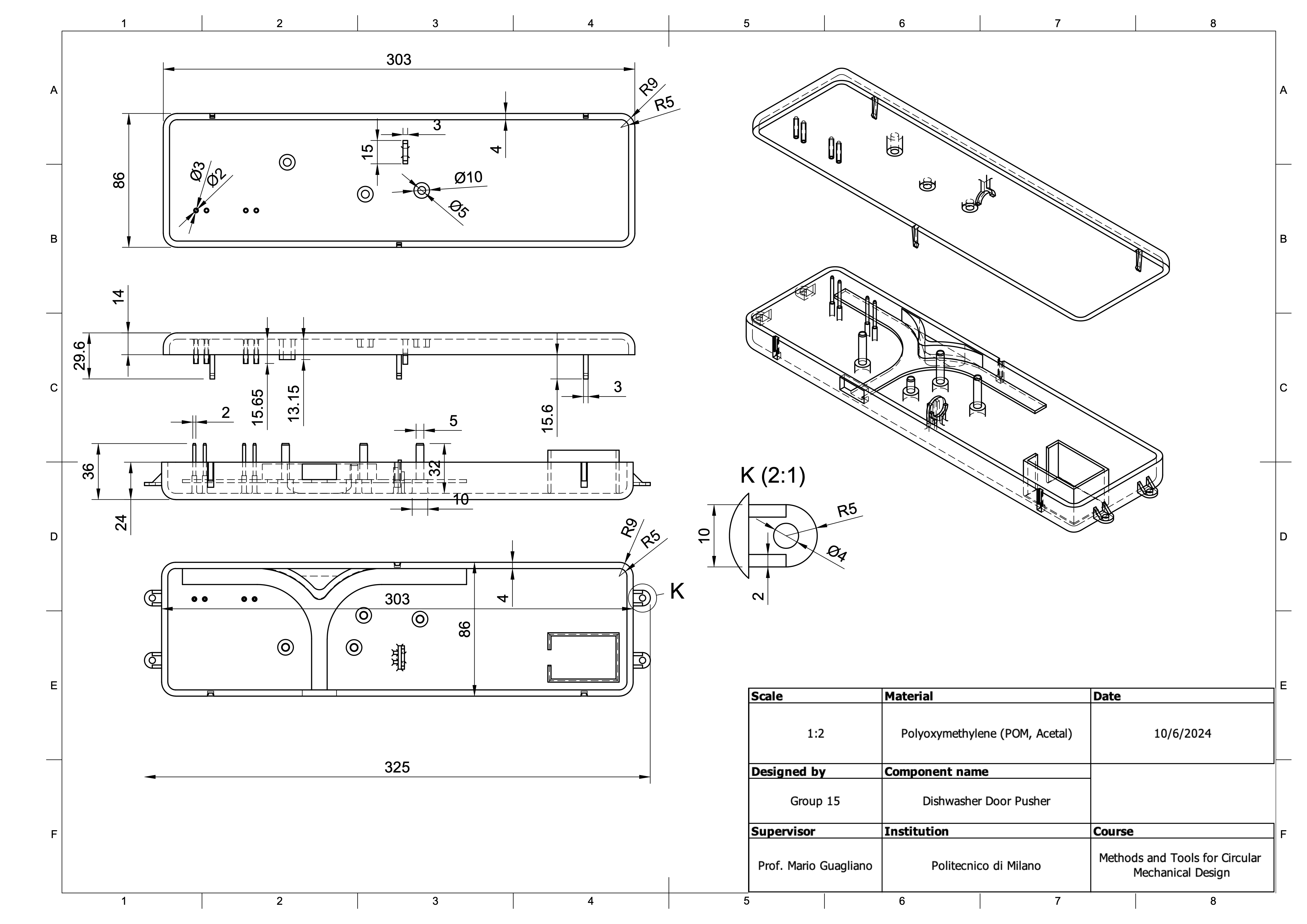
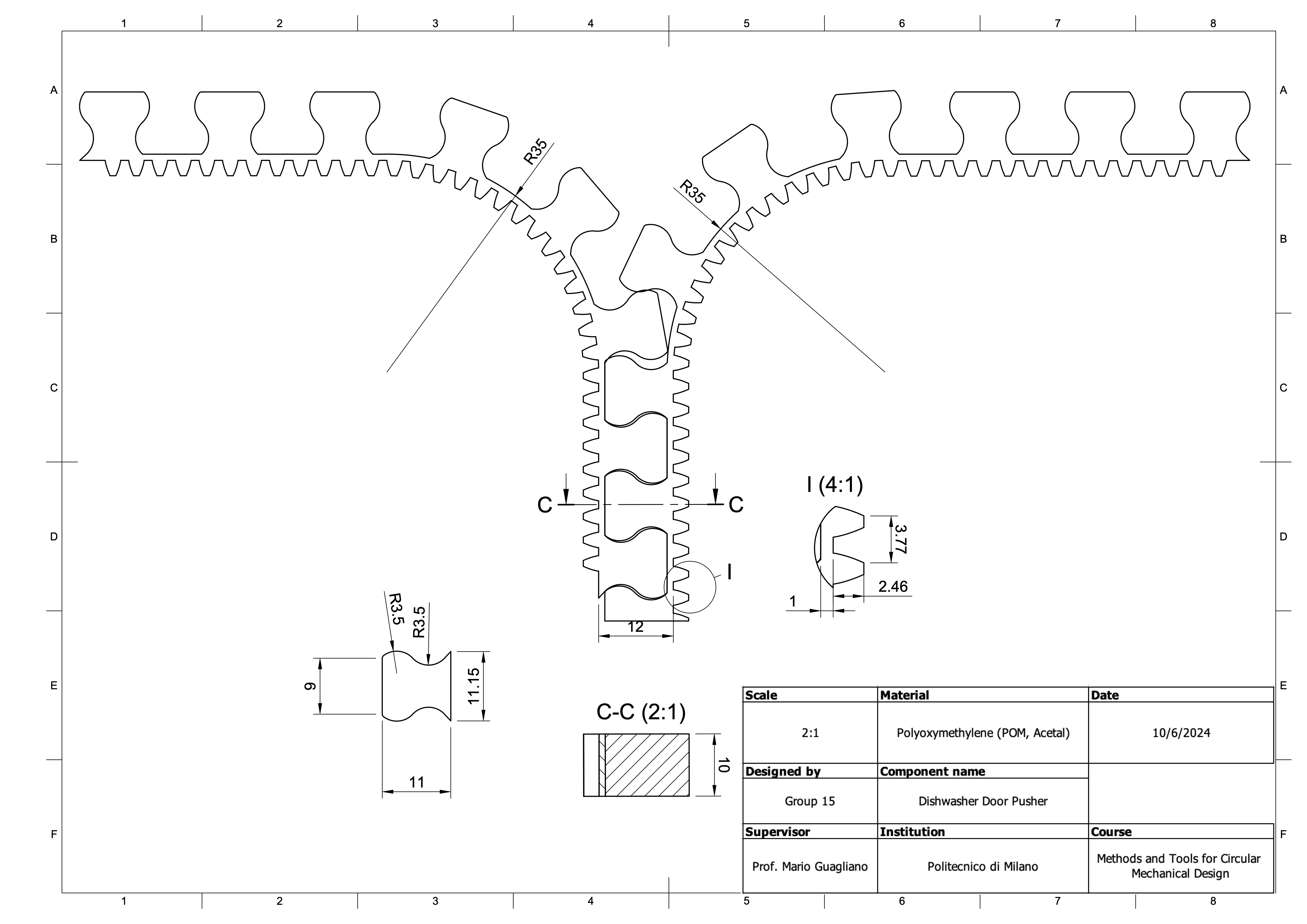
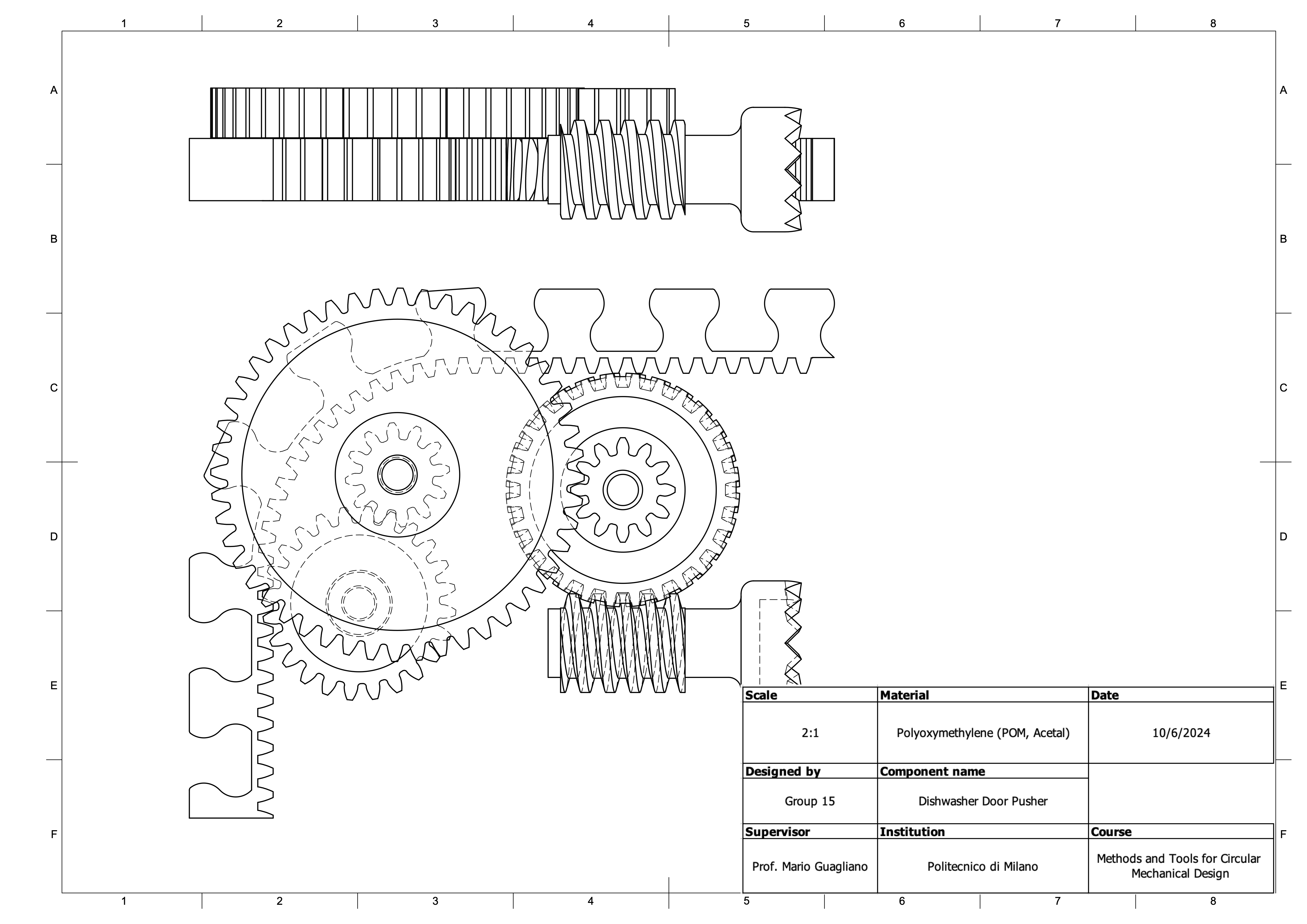
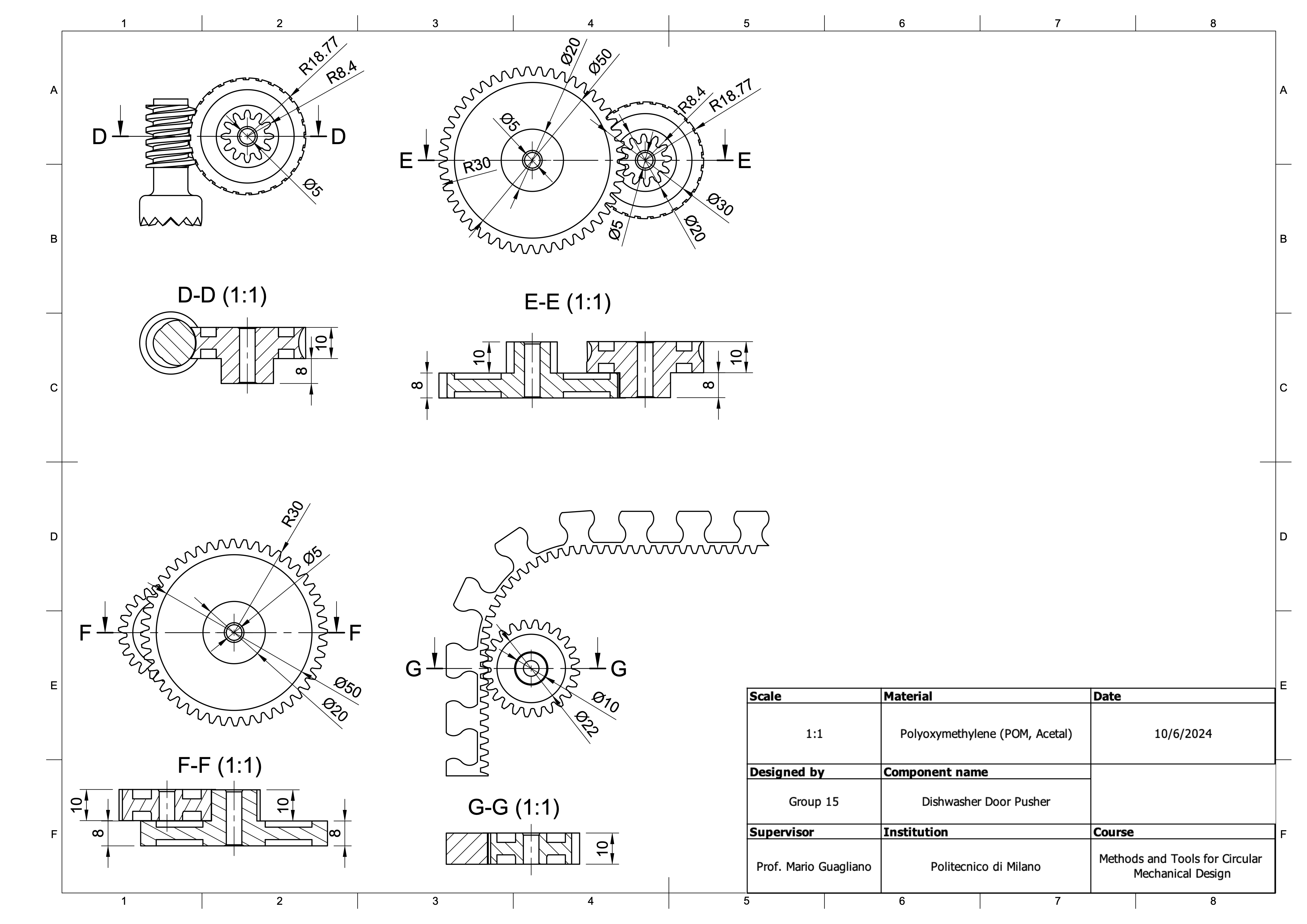
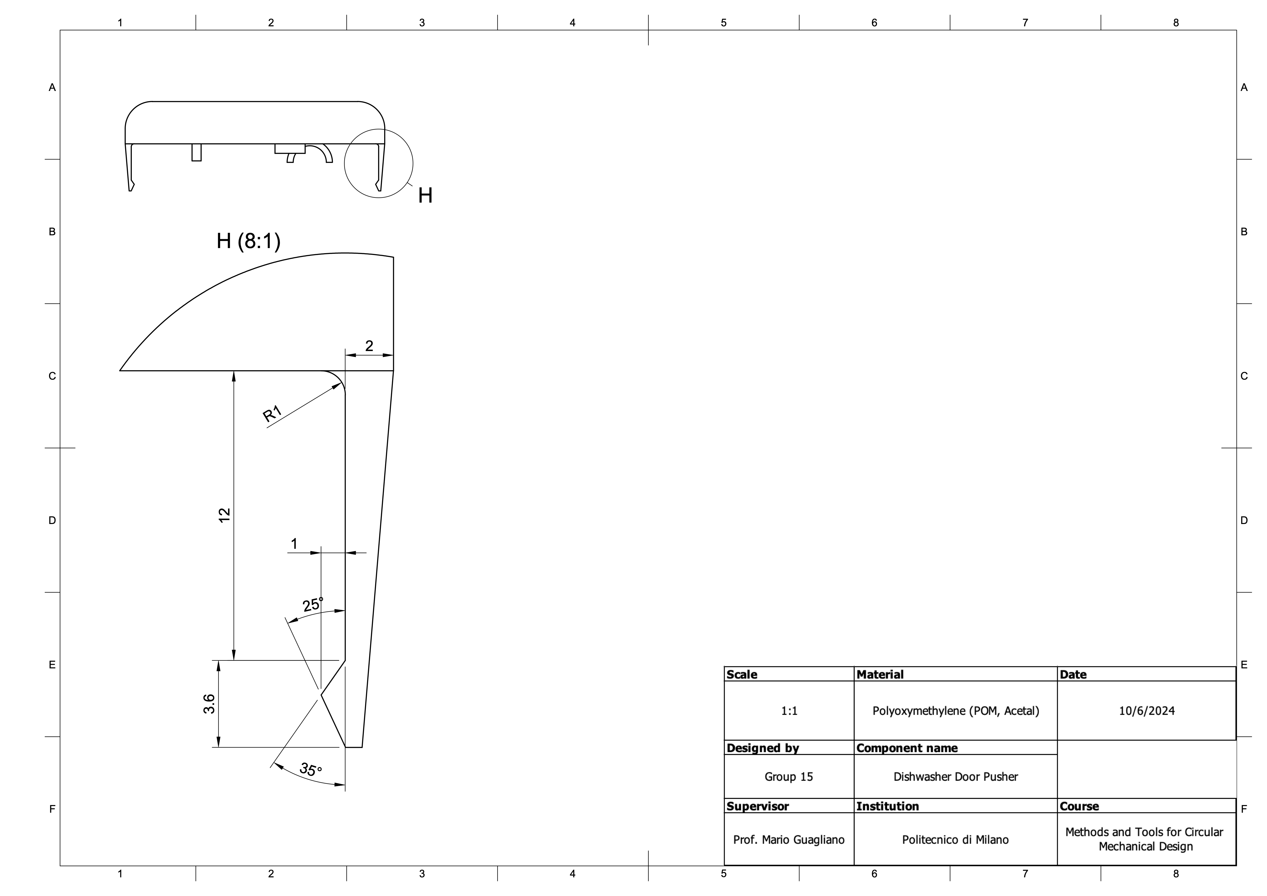
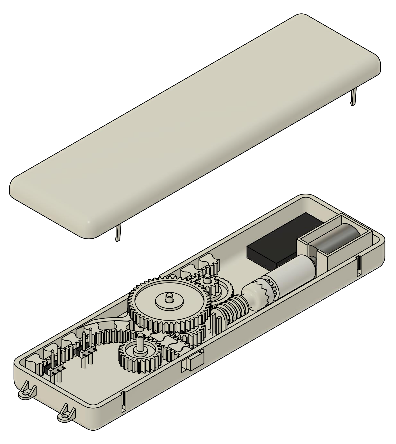
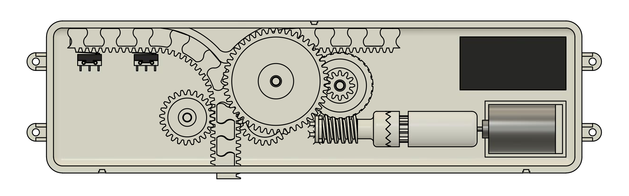
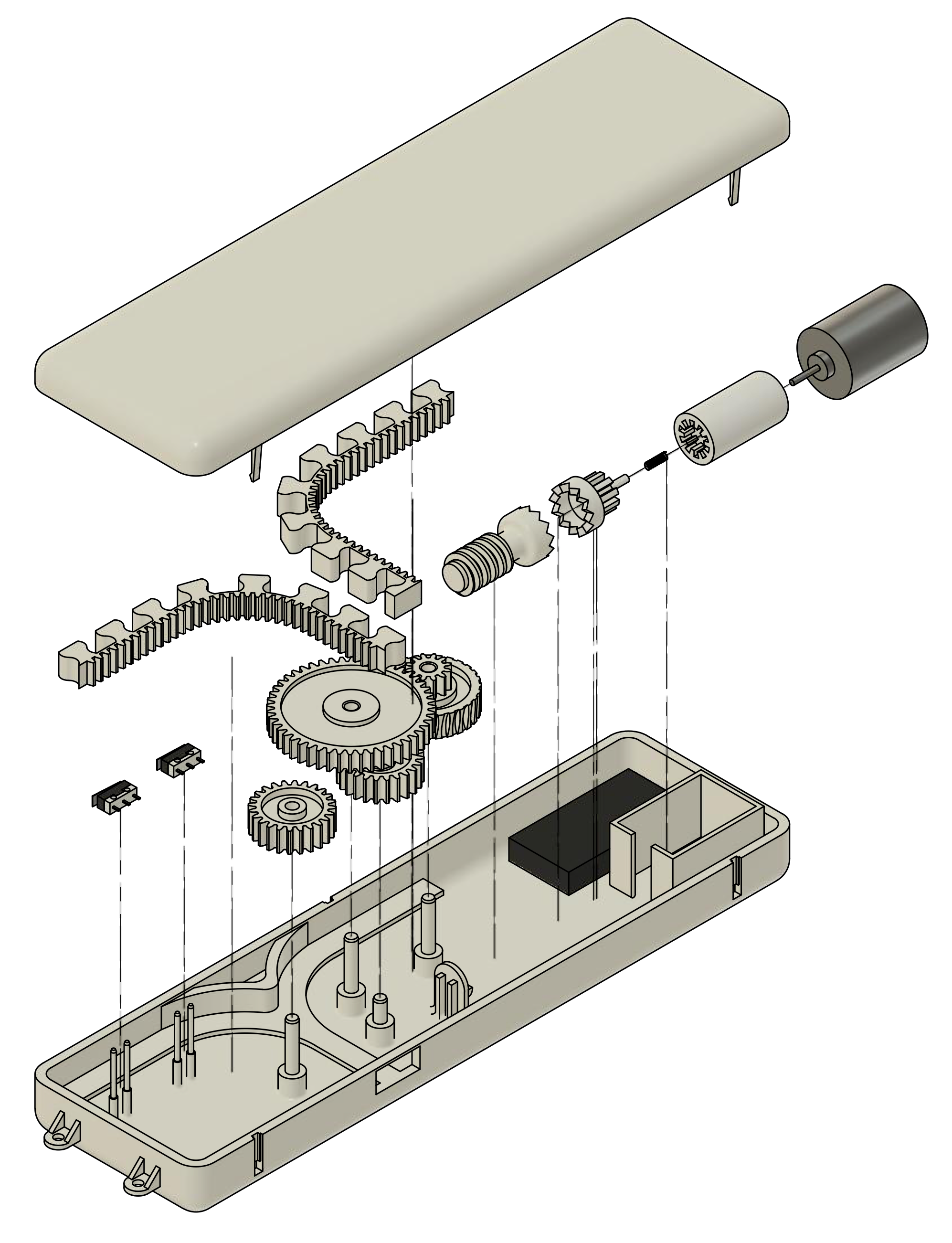
This was a design project for a university course - I designed a new dishwasher part which pushed open the dishwasher door at the end of the cycle, to allow steam to escape. The flexible “zipper” was utilized to achieve a sufficient stroke length, but in a constrained space when retracted. I also designed a slip clutch which disengaged when the force on the zipper was too high (i.e. if there was an obstruction or something was jammed).
The design was parametrically modelled in Autodesk Fusion, which allowed for a model which could easily be tweaked as the design changed. It was my first time using parametric modelling (being used to the ephemerality of direct modelling in Rhino), so there was a steep learning curve but I’ve learned a lot about how to do it. As I learned, the process of parametric modelling relies heavily on a smart and consistent definition of parameters (distances, angles, etc). Taking a few minutes at the start of modelling each component to think about what the important parameters are can make future work a million times easier.
I had to recreate some parts from reference drawings - limit switches and the motor. Interestingly I found this process to be quite straightforward, as long as the reference drawings were clearly labelled. The reference drawings I created were easy enough to create in Fusion, given that all the data is contained within the program.
All the parts (besides the motor, control board, spring, and limit switches) were designed to be injection moulded out of POM. There were many different aspects of this design which ensured the quality and sustainability of the product. The key processes were: material selection, strength analysis (e.g. buckling, fatigue, bending), snap-fit joint design, gear ratioing and design, slip clutch design, injection mouldability, costing, assembly analysis, environmental impact, failure mode and effect analysis, end-of-life analysis.
Overall, I found this to be an incredibly challenging project, but one from which I learned so much about. I learned all the stages of responsibility creating a product which is to have market viability. If I were to do the project again, I would take some more time at the start to plan out the workflow of the modelling, making sure to finalise the key features before actualising it in a parametric model.
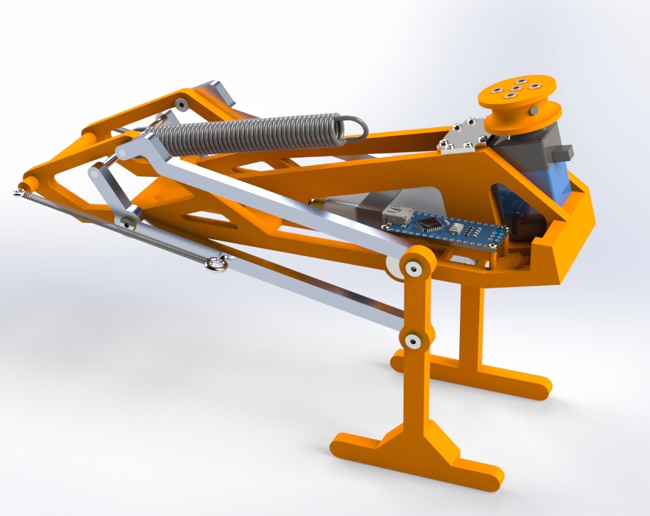
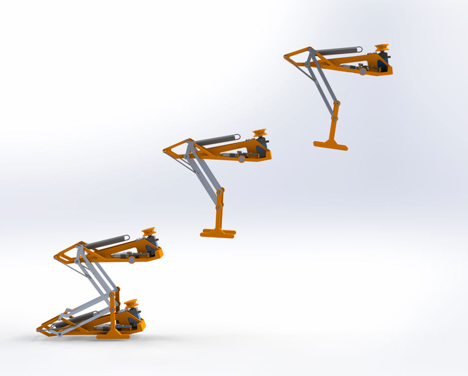
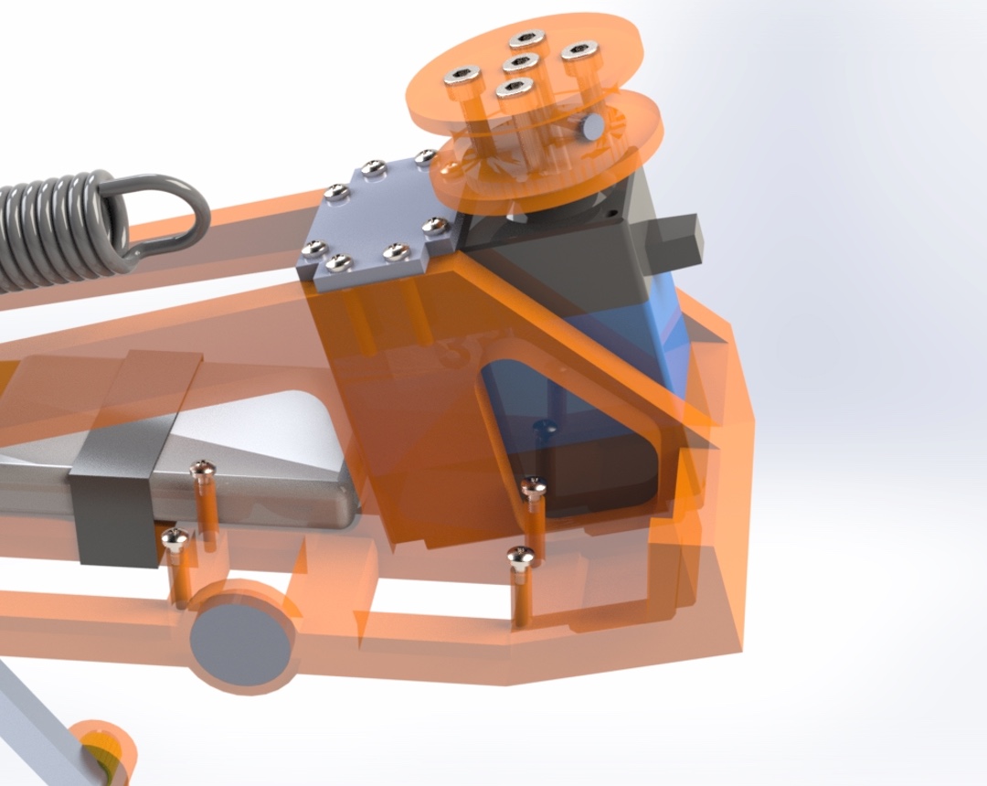
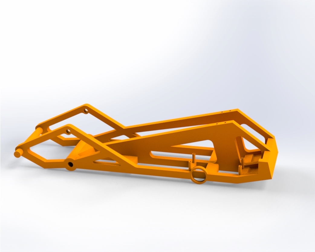
This was a group design project for a university course - we (myself, Alex, Alfredo, Morgan, and Dongrun) designed a robot using parts which can be purchased or additively manufactured (most of the body is to be made of PLA, with a few aluminium pieces for extra strength).
The robot has a clever geometry (inspired directly by the locust) which allows the storage of a lot of potential energy in the springs, to be released in a very short amount of time - this snappy dynamic allows the robot to theoretically jump ~70cm high, and 2.1m forwards.
We designed the geometry parametrically, and modelled the dynamics in Matlab using Lagrangian mechanics. This was then modelled in Solidworks using manufacturable/purchasable components (including an Arduino nano, a servo motor, an onboard battery). The new parameters (masses, moments of inertia, etc) were then updated in Matlab accordingly - through this iterative process we eventually landed on a final design.
info
I'm particularly interested in giving a second life to scrap materials, and experimenting with unconventional materials to create aesthetically pleasing and functional designs.
instagram: @homie.from.the.way.back
email: tidhar.tom@gmail.com